THE BASIC TERMS OF HAMM MACHINE TECHNOLOGY
Hamm is one of the earliest manufacturers of rollers in the world. Through continuous development, up to now, the company has researched and created the most advanced technologies equipped for rollers. It is the result of practical testing, listening to customers' difficulties to create the best quality rollers.
VIDEO: BASIC TECHNOLOGY ON HAMM
Part 1
Part 2
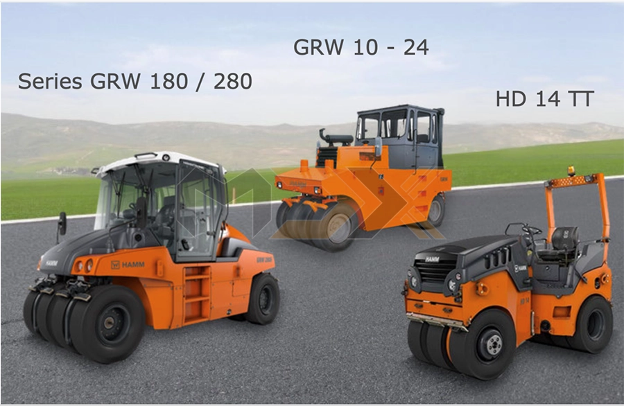
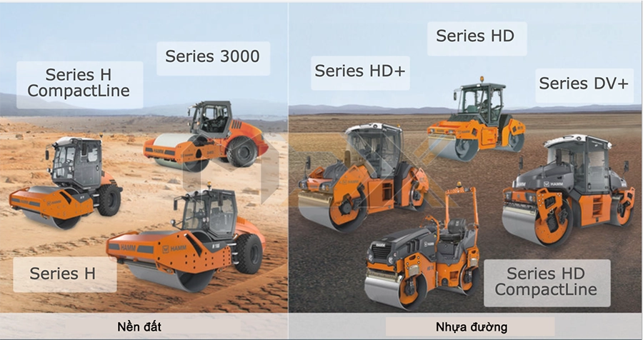
WHAT ROLLER TYPES ARE OFFERED BY HAMM?
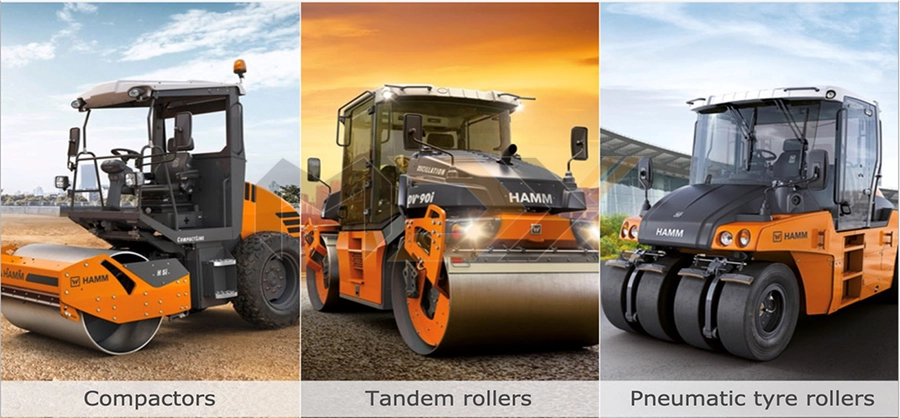
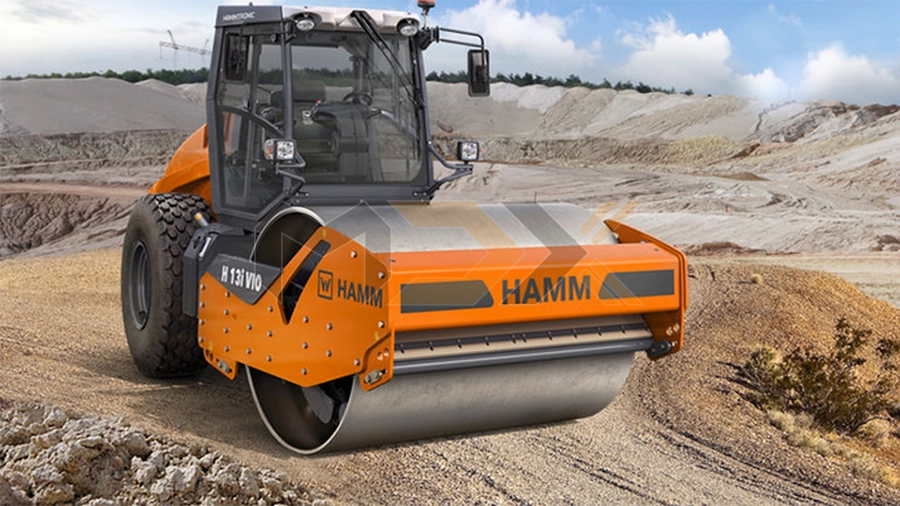
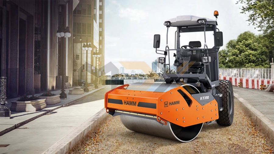
Roller type I: Compactors
See more product at: HERE
The front of a compactor comprises a smooth drum equipped with vibration or VIO or a padfoot drum with vibration; the rear of the compactor has two driven profile tyres. In Hamm compactors, both the drum (in standard and optional models) as well as the wheels or rear axle are driven.
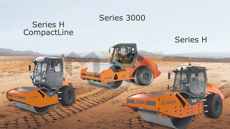
Product range
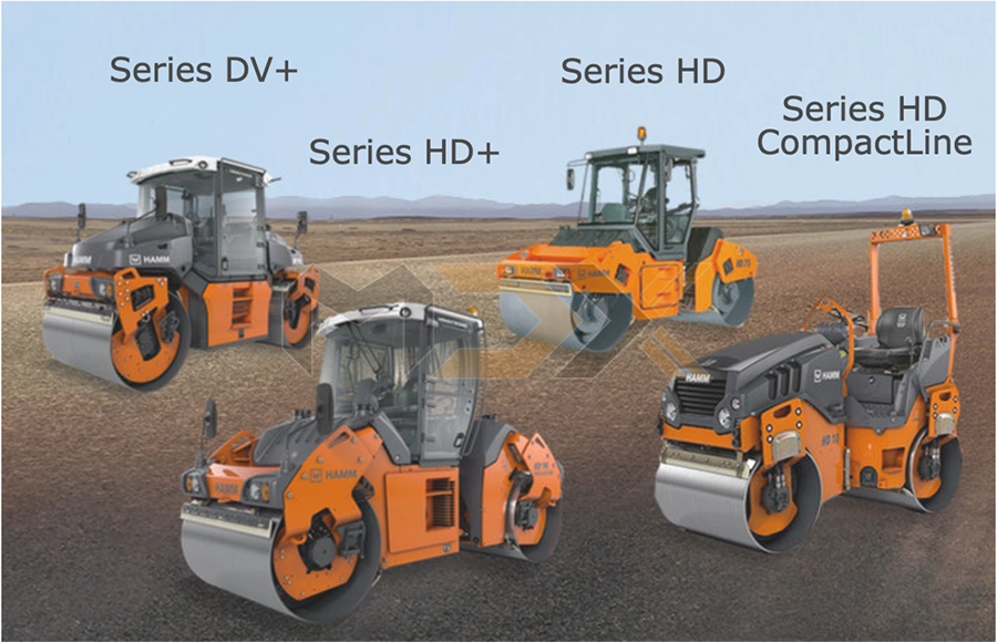
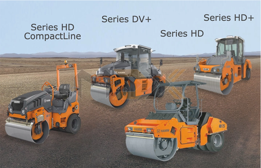
Roller type II: Tandem rollers
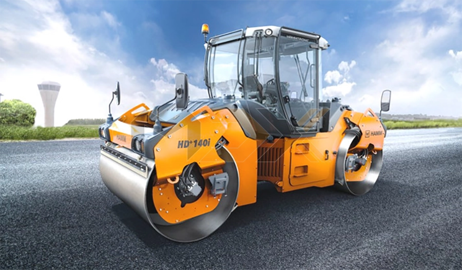
See more product at: HERE
A tandem roller is equipped with a drum at the front and rear respectively. These can be equipped with a vibration drum, oscillation drum or split vibrating roller drum. Hamm tandem rollers are fitted with a hydrostatic drive and vibrating drive.
Product range
The combination roller is a special type of the tandem roller. Combination rollers can be articulated or all-wheel steered rollers whereby one axle has rubber wheels assembled on it and the other axle has a smooth drum. The rubber tyres are mounted in the centre with a slight clearance.
Product range
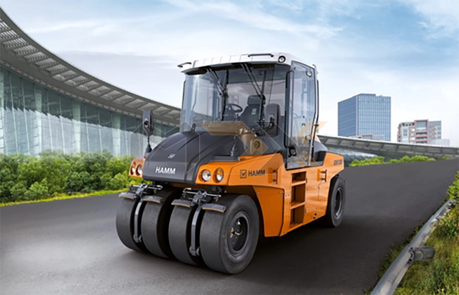
Roller type III: Pneumatic tyre rollers
See more product at: HERE
4 rubber wheels (smooth tyres) are installed with small spacings on each axle respectively. The rubber wheels on the front and rear axles overlap each other reciprocally. Rubber wheeled rollers compact statically using the dead weight of the machine. The compaction effect and depth depends on the wheel load, the internal tyre pressure and the roller speed.
Product range
INTRODUCTION TO STEERING METHODS
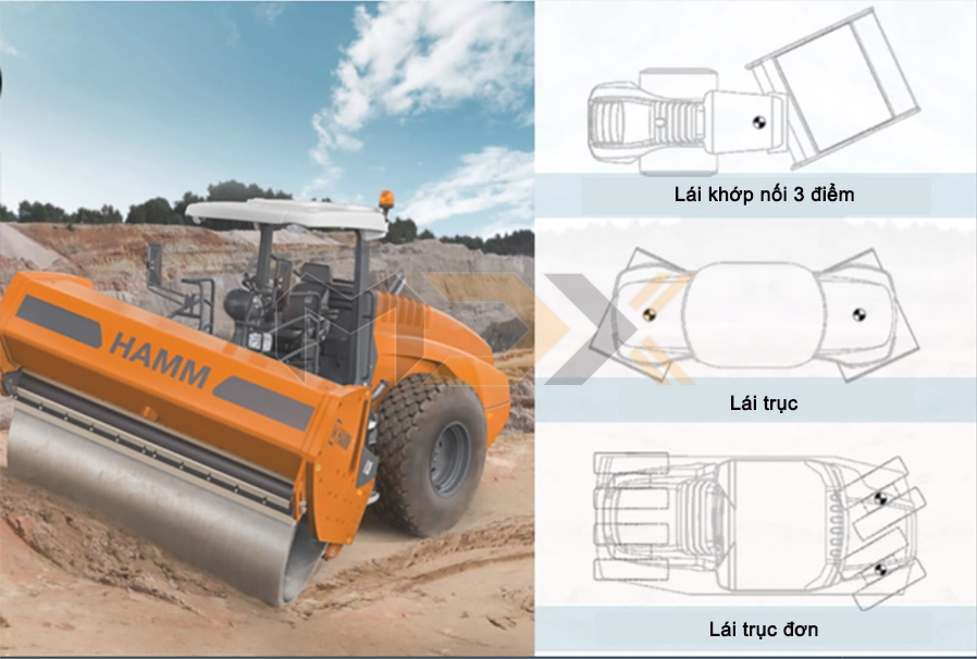
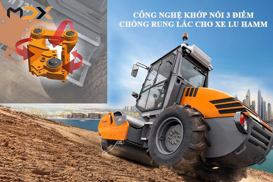
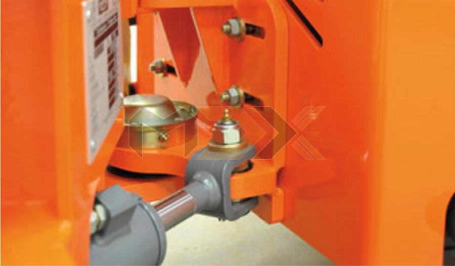
The 3-point pendulum articulated joint
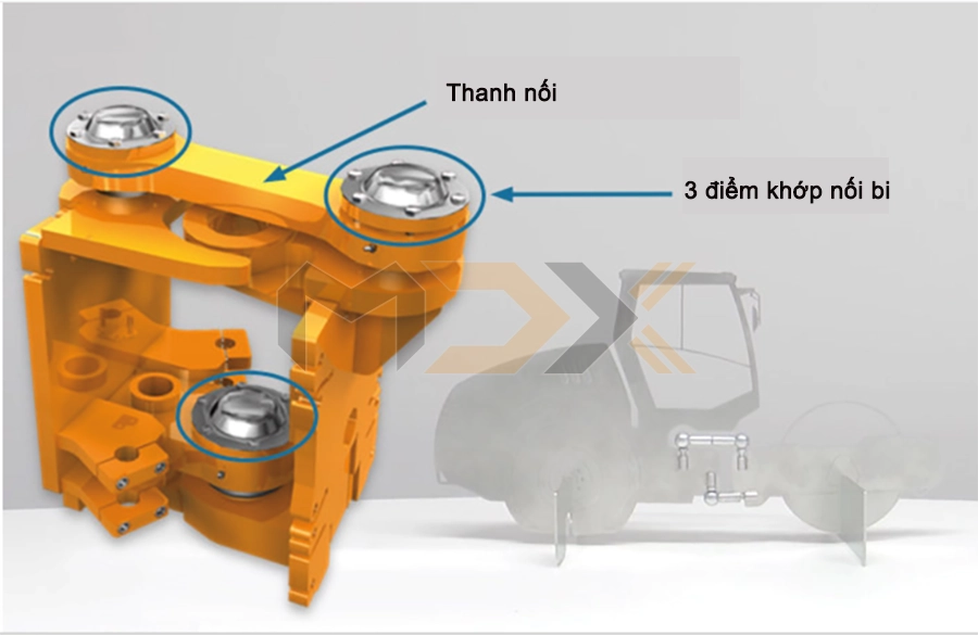
Hamm does not utilise a conventional articulated joint, rather a special construction design: The 3-point pendulum articulated joint. This allows the machine to be steered and the drum to be oscillated at the same time.
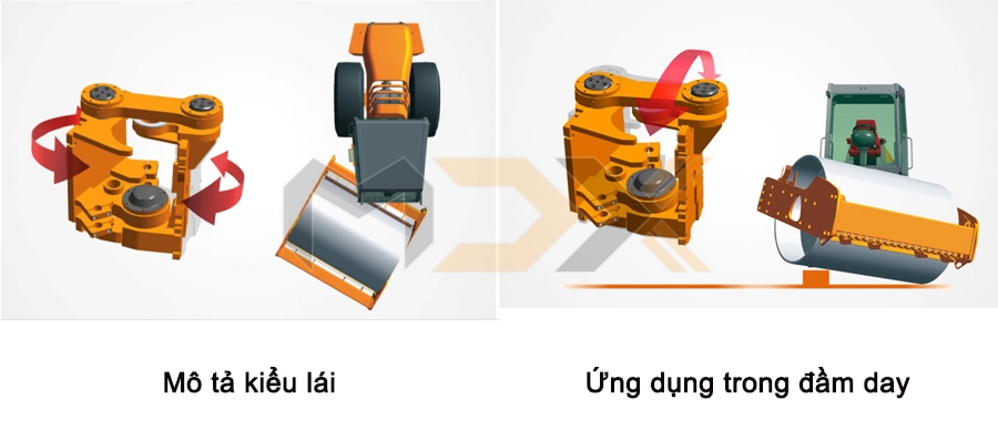
Steering - Oscillation
The 3-point pendulum articulated joint method:
- The front and rear carriages of the machine are connected by a joint.
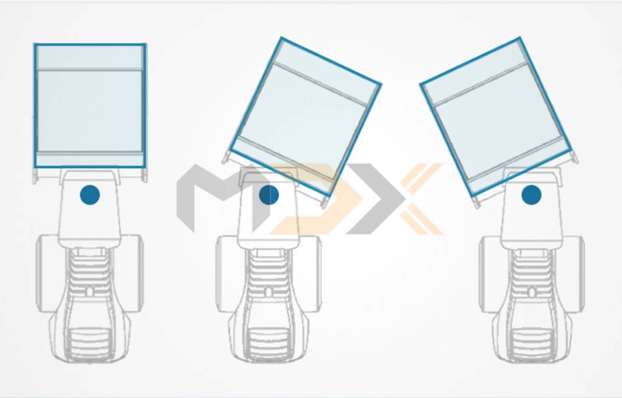
- The change in direction is executed by horizontal pivoting (or articulating) of the vehicle parts including the therein located drums and/or wheelsets.
Features of the 3-point pendulum articulated joint:
- Excellent on-centre-feel: The centre of gravity of the machine increases on the curve. The centre of gravity of the machine is at its lowest during on-centre run. The machine therefore has a perfect on-centre run and automatically keeps its direction.
- Even weight distribution: On the curve, the machine does not lean so strongly towards the outside of the curve. The difference between the weight on the inside and the outside is only about 30% of the difference of a conventional machine.
- Damping for impacts: Unevenness in the ground is not just transferred upwards but part of the movement is also transferred laterally.
- Increased tilt stability: The direction of thrust of the drive axle is diverted by the upper pendulum arm, thereby halving the angle of the thrust axle.
See more at: HERE
Articulated rollers: Product range
The pivot steering method
The front and rear drums of the machine are both connected respectively to the chassis with a pivot. The change in direction is executed by steering the front or rear drum or by simultaneously steering both drums. The centre of gravity of the machine is always on the longitudinal (roll) axis. Load distribution remains identical on-centre and in the curve.
Each drum is steered individually or jointly (analogue) via two pivots. Advantages:
- Absolute even weight distribution
- No shift in the centre of gravity
- Manoeuvrability of the machine
By steering using two pivots, the machine provides special steering methods and can therefore be used in a multitude of situations.
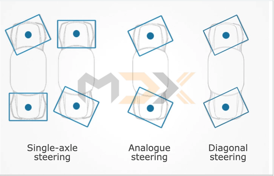
SINGLE-AXLE STEERING
Only one of the two drums will be steered with single-axle steering. The drums are only in-line during an on-centre run. In the curve, the uncontrolled drums always have a narrower radius than the steered drums. In some circumstances, the tracks of the two drums will therefore not completely overlap on the curve.
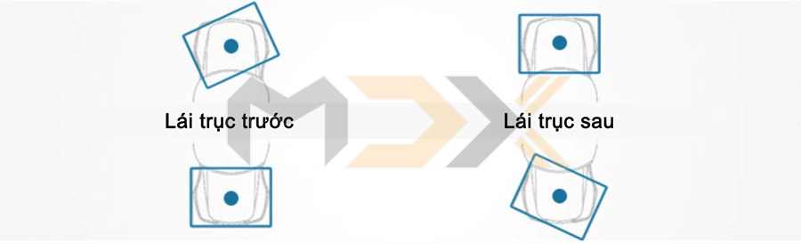
| Front-axle steering | Rear-axle steering | |
| Steering wheel | Steering the front drum with the steering wheel | Steering the rear drum with the steering wheel |
| Switch for track offset | Steering the rear drum with the switch for track offset | Steering the front drum with the switch for track offset |
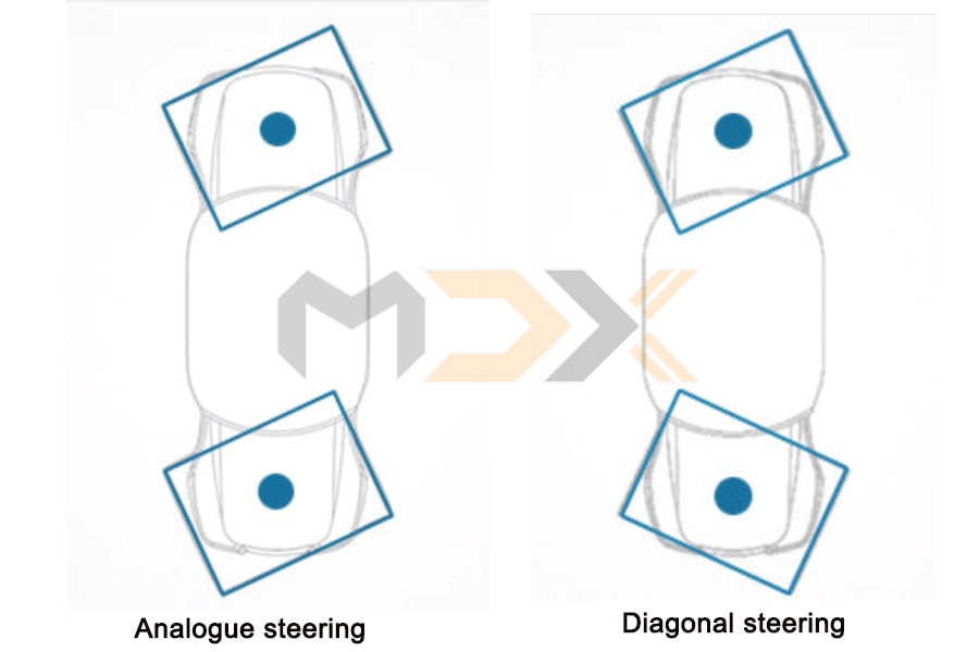
Analogue steering
In analogue steering, both axles are steered in the respective opposite direction at the same time. Both axles react at the same time to steering commands from the steering wheel. The front and rear drum therefore run on a line even in the curve, and have the same radius. Analogue steering increases the possible steering angle and therefore allows for a very small turning track. The rear drum can also always be steered with the switch during analogue steering.
Diagonal steering
In diagonal steering, both axles are steered by the switch for track offset at the same time and in the same direction. This results in a faster, lateral track offset. If the machine is controlled by the steering wheel, the drums run in opposite directions (see analogue steering).
Track offset steering mode
Track offset is a special steering method available both in articulated as well as pivot-steered rollers. Track offset is often also referred to colloquially as crab steering.
- No track offset: When there is no track offset, the front an rear drums run parallel one behind the other. The front and the rear drum therefore run in a track.
-Track offset: Both drums run offset to each other with the track offset. Therefore the tracks of the front and rear drums do not overlap each other with 100%. Advantages:
+ Reduced cutting marks
+ Edge work at curb stone, because slight steering movements are impossible
+ Increased working width when “ironing out”
+ Bulge-pressing (using the edge pressing and cutting equipment)
TRACK OFFSET - TECHNICAL IMPLEMENTATION
MECHANICALLY
Series HD CompactLine: Move the rear drum by releasing and tightening screws at the 3-point articulation (slotted hole). Permanent offset.
HYDRAULICALLY
Series HD, Series HD+: Move the rear carriage using a steering cylinder. Operate with buttons on the display.
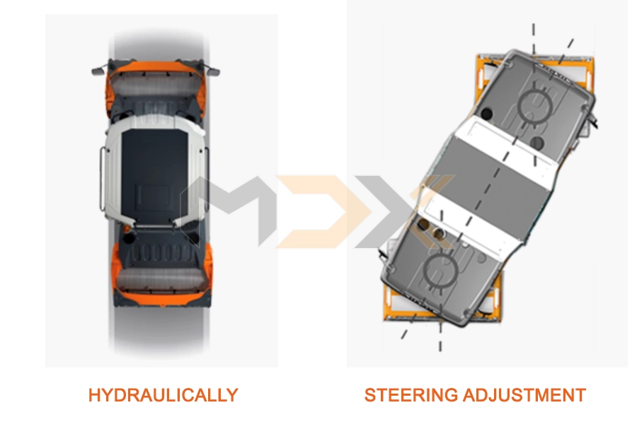
STEERING ADJUSTMENT
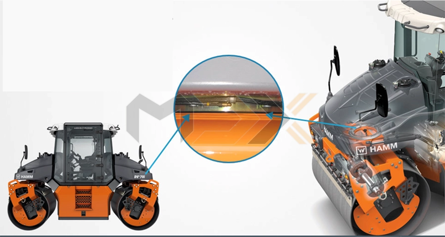
Series DV+: Steer the front and rear drum in the same direction.
STEERING WITH PNEUMATIC TYRE ROLLERS
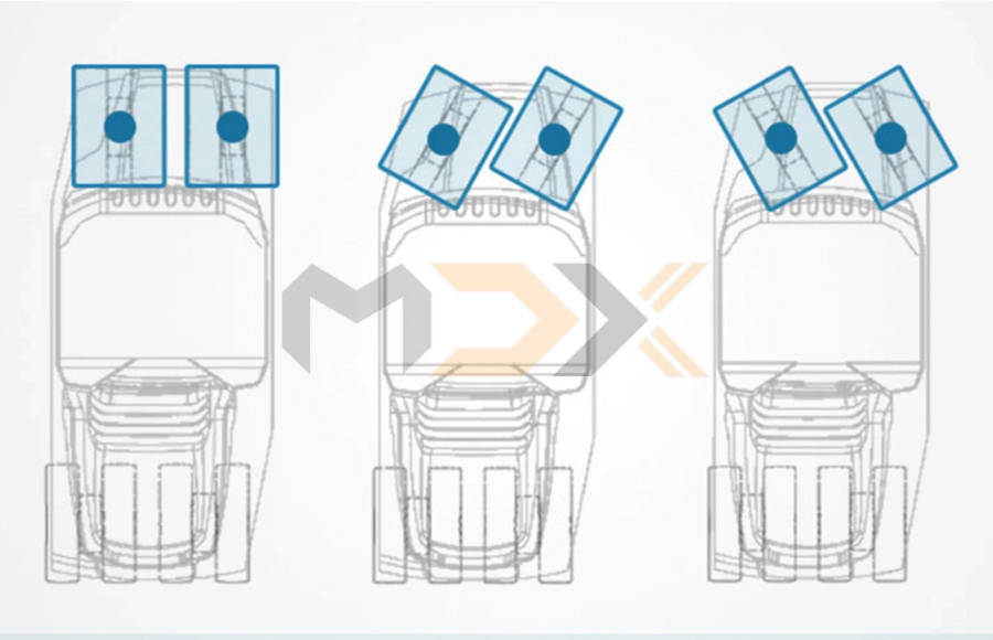
Front-axle steering: Only the front axle is controlled using pneumatic tyre rollers (as with a car). The single wheel pairs are moved here via two steering points. They therefore remain within the area of the frame. This provides the machine with more stability. The 8 wheels of the pneumatic tyre rollers (4 front + 4 rear) overlap.
SPRINKLING METHODS
Sprinkling plays an important role in all asphalt rollers. There are two different sprinkling methods here (for drums and for rubber tyres).
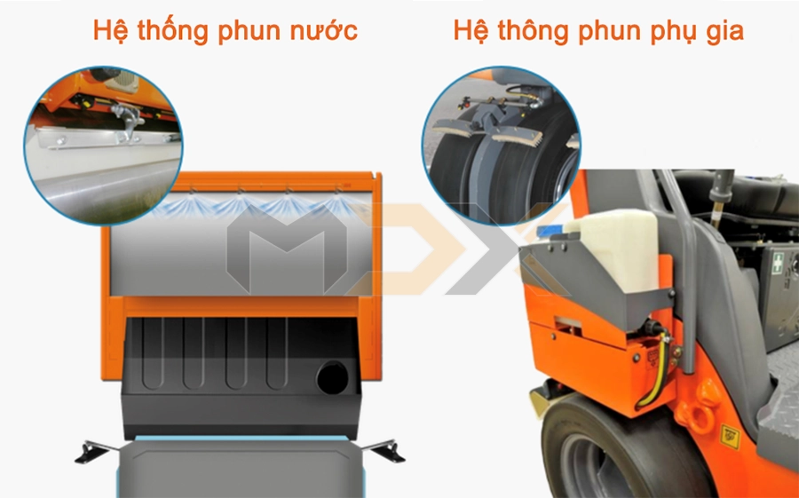
Combination roller sprinkling systems: Two sprinkling systems are built into combination rollers - water sprinkling for the drums and additive for the wheels.
Water sprinkling system: The smooth rollers are sprinkled with water from fine nozzles to prevent hot asphalt from adhering to the smooth rollers.
Additive sprinkling system: The cold rubber wheels are sprinkled with a specialised separating agent (additive) to prevent hot asphalt from adhering to them.
Hamm provides an applicable asphalt separating agent “Wirtgen Group Asphalt AntiStick” for rubber wheeled and combination rollers. The advantage with this separating agent is that the wheels do not adhere and are not damaged.
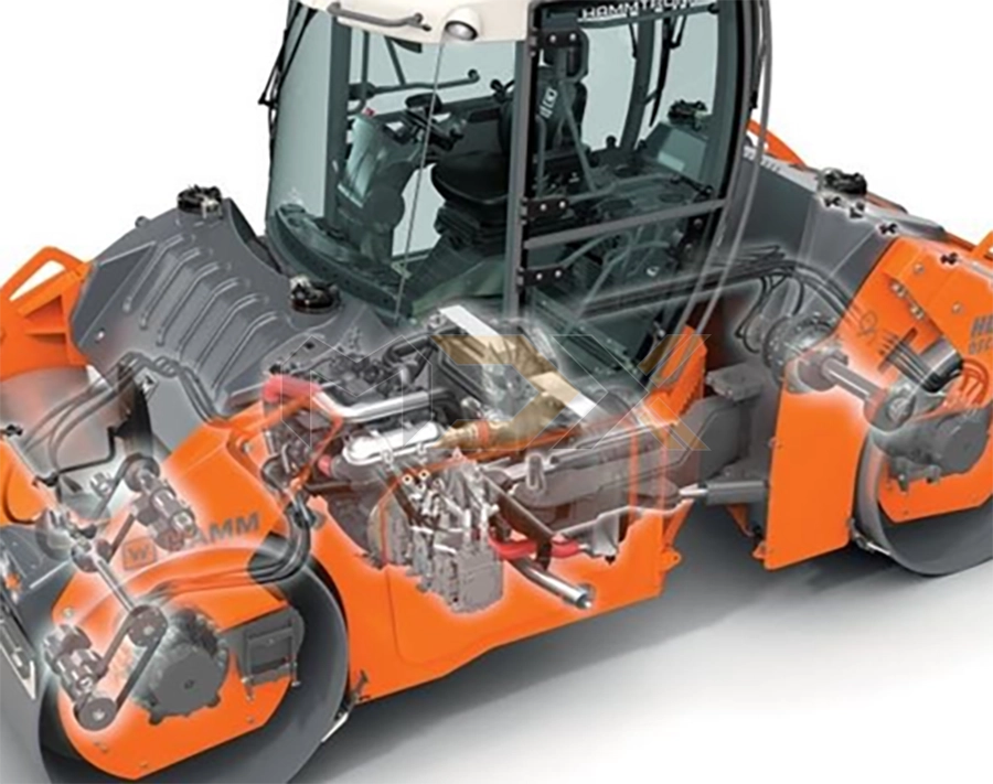
DIESEL ENGINE
In general, construction machinery is driven by a diesel engine. Hamm uses engines manufactured by Deutz and Kubota. Other drive components are the drum drive and the axle drive.
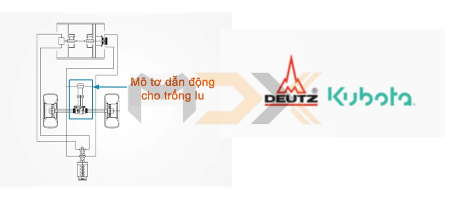
DRUM DRIVE
- Drum traction drive compactors: For the 3410/3411 series, there is also a version without drum drive (3410x or 3411x)
- Drum traction tandem rollers: Each drum of a non-split drum is driven. When the drum is split, each half of the drum is driven.
AXEL
There are two possibilities for axle drive. Either one axle is installed with differential (“limited slip”) or the tyres are driven by wheel motors.
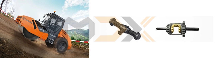
Differential (“limited slip”)
- An axle with a differential prevents the wheels from spinning and/or improves the drive torque of the machine
- Advantages: The lock is always automatically effective. It prevents single-sided tyre slip and considerably reduces tyre wear. Smooth running. Simple and robust design. Automatic distribution of the drive torque to the wheels. Driver does not need to intervene.
WHEEL MOTORS
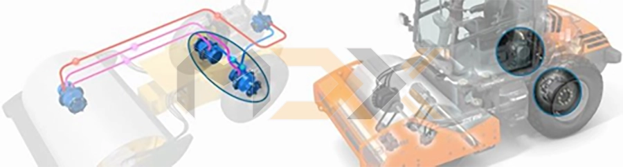
Wheel motors (for H 5i and H 7i)
Tyres are no longer driven by an axle but each tyre is driven by its own tyre motor. Force distribution on the rear wheels is approx. 50:50 (this is not a differential lock).
- Advantages: Compact design. Low centre of gravity of weight and machine. Torque distribution “without” energy loss. Automatic and always active.
- Disadvantage: No differential lock between the wheel motors.
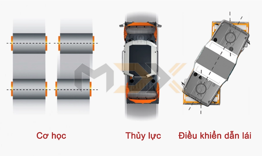
DRIVE TECHNOLOGY: DRIVE TYPES
An additional criteria in differentiating the machines is the drive types.
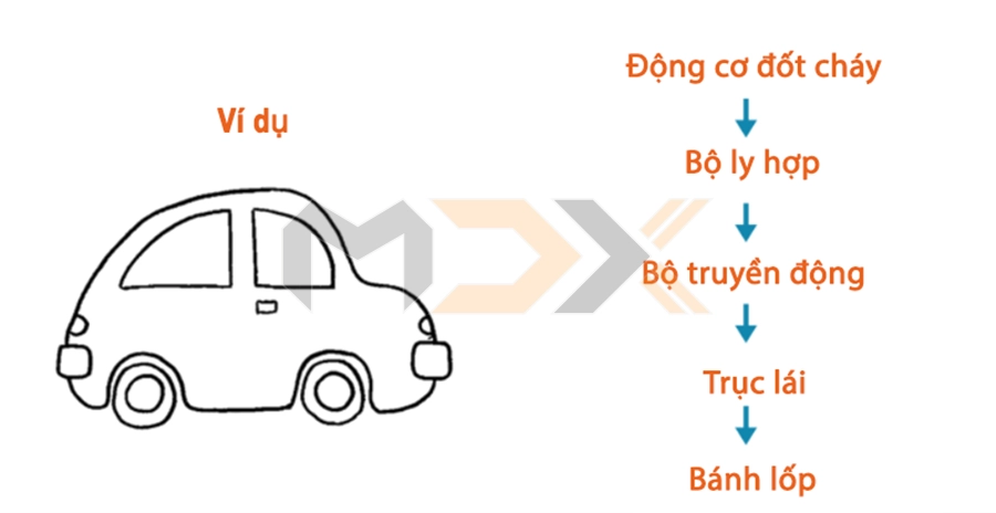
- Mechanical drive: With mechanical drives, there must be a direct connection between the engine, transmission and differential. The position of the transmission is therefore largely determined by the position of the engine.
Hydraulic drive: The hydraulic drive unit enables a disbanded, flexible design method and an optimal alignment for the space demands. The connection between the engine and the pump is created by pipework and hose lines which can normally be installed freely. Advantages:
- Optimal design adjustment of the hydraulics to the space requirements
- Decentralised use of hydraulic energy
- Stepless speed adjustment of the drive within very wide limits, easy reversal of the direction of movement
- Transmission of high torques and large amount of energy possible at low overall installed size
- Movements under full load can even be initiated from standstill
- Power and speed can be controlled steplessly.
- High cost effectiveness due to central drive systems
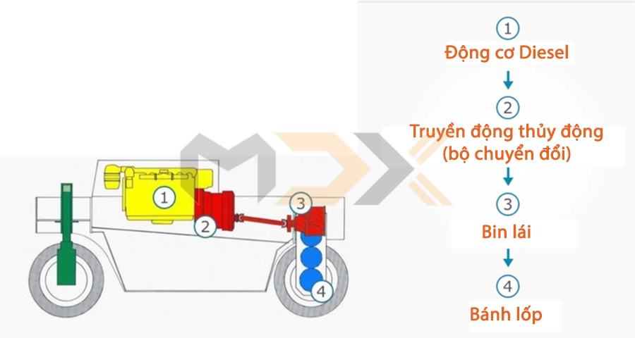
Drive technology: Hydraulic drive – hydrodynamic
Hydrodynamic drive (GRW 10-24): The drive torque from the combustion power unit (engine) will be converted into kinetic energy (rotary motion) via a hydrodynamic transmission (converter) in a hydrodynamic drive unit. The GRW 10-24 is the only model series driven hydrodynamically.
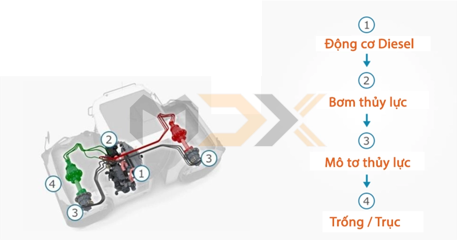
Drive technology: Hydraulic drive – hydrostatic
Hydrostatic drive: The mechanical energy from the combustion power unit (engine) will be converted into hydraulic energy by a pump in a hydrostatic drive unit. The hydraulic circuit will transport this to the drive engines, and it will be converted there into a rotary motion. The hydrostatic drive permits responsive driving of the machine and smooth acceleration and braking.. Example: Series HD+
TYRE EQUIPMENT
The machine tyres play an important role. In addition to the rubber mixture, which is responsible for the appropriate traction, the sub-base is decisive for handling. In principle, the design of a tyre is identical. On the inside there is an airtight rubber layer which assumes the function of the tube in a tubeless tyre. One or several layers made of various fabrics or synthetic fibres are placed over this (referred to as carcass ply). They are responsible for the shape and the rigidity of the tyre. Over this, depending on the design, is a tyre belt or the immediate rubber layer comprised of natural rubber, grime, sulphur and lots of undisclosed chemicals.
We differentiate today between bias and radial tyres. The main difference between bias and radial tyres is their arrangement and the number of carcass plys.
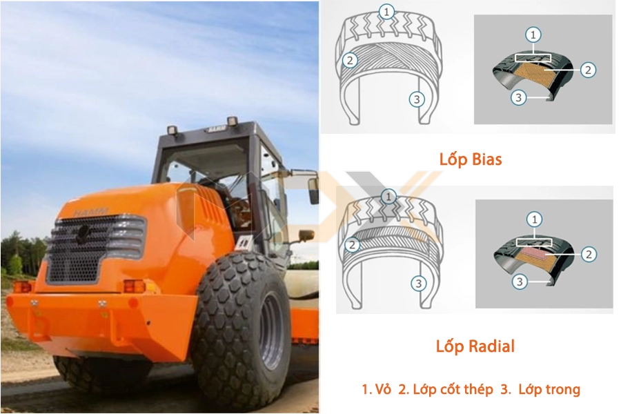
BIAS TYRES
Design: Bias tyres have several layers with strands running diagonally at angels of around 25 to 35 degrees. This arrangement makes the tyres very rigid and with solid flanks. The spacing surface of the bias tyre is rather round.
Advantages: High vehicle stability. High resistance to side wall damages. Self-cleaning on loamy soil. Can be used in all terrains (hard and unsurfaced). Can be used with high tyre load
Disadvantages: Fast heating of tyres, especially at higher driving speeds. Not as comfortable due to increased hardness of tyre
RADIAL TYRES
Design: Radial tyres have steel plys. The carcass plys are arranged 90 degrees to the direction of wheel travel. Mostly just one and a maximum of two layers are used, with the tyre belts wrapped around them. The lowest layer contains the steel plys, providing the tyre with its most important feature. The spacing surface of the radial tyre is rather flat.
Advantages: Good steering and improved road contact. High driving comfort. Low heat development. Insensitive to damage on the running surface. Less tyre wear. Even wear. Better grip (especially on wet tracks and in curves). High level of rigidity. Good running characteristics.
Disadvantages: Due to its hard tread, the tyre causes increased running noise. More susceptible due to soft side walls. Small uneven parts of the road are not absorbed as well because the radial tyre is fitted with a steel belt
Use of bias tyres/radial tyres (manufacturer)
Tyres for compactors in earth work
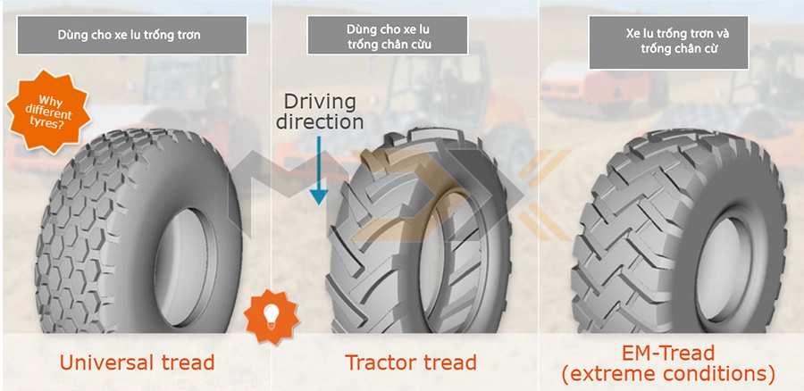
Universal tread
Advantages: Less tyre imprint. Less damage to the surface of the ground. Good traction for most utilisation cases.
Disadvantage: Worse traction on the material as the tread degrades quickly (e.g binding ground)
Why are different tyres used? The tyres play an important role, especially in earth work. In particular, they influence the traction and climbing ability of the machine, but also the imprint of the tyres on the ground. Different tyre types are therefore used. All-purpose and tractor tyres are bias tyres.
Tractor tread
Advantages: Good traction, among others with binding material. Better self-cleaning
Disadvantage: Lots of tyre marks.
Attention: The tyre drive direction is important! The best effect will be achieved in the recommended driving direction.
EM-Tread (extreme conditions)
Advantages: Resistant against sharp-edged material. Good running characteristics on hard abrasive sub-bases/ground. Increased durability
Disadvantage: Worse traction (especially with binding material).
EM means Earth Mover. The driving direction is irrelevant for these tyres.
Tyres for compacting in asphalt construction
As these tyres are used in hot asphalt construction, sprinkling is particularly important. A tyre is normally heat resistant up to approx. 120 °C, i.e. it could be damaged at higher temperatures. The tyre must therefore be continuously sprinkled to keep its temperature below the critical value.
ASC - TRACTION CONTROL
Traction control (also referred to as anti-slip control - ASR) plays an important role in many machines. The following pages provide you with a short overview of the various systems.
1. Manual torque pre-selection (for compactors)
2. Traction control (for compactors with Hammtronic)
3. Hydraulic (traction control for compactors)
4. Hydraulic (traction control for tandem rollers)
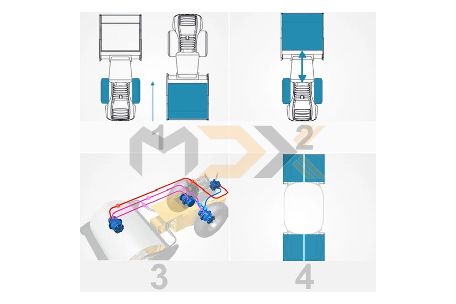
Torque pre-selection of drive axle (manual)
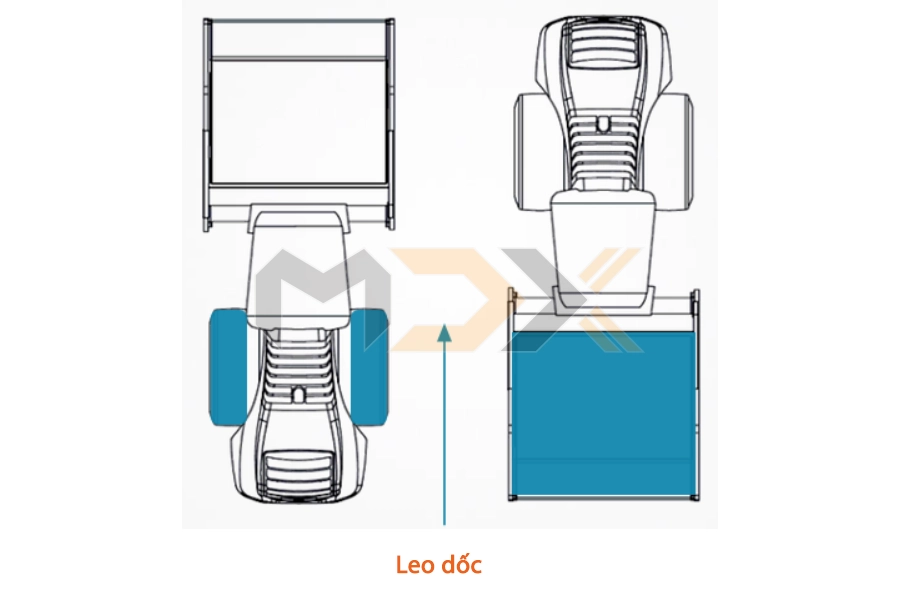
Pre-selection switch, mountain switch: The torque on the rear wheels or on the drum is increased depending on whether the machine is in forward or reverse when climbing. When climbing with the wheels at the rear, a high torque is generated on the rear wheels, when climbing with the drum at rear, the increased torque is on the drum.
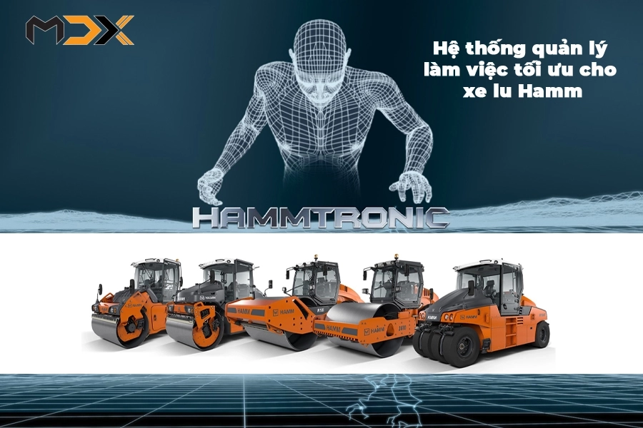
Traction control with Hammtronic
ASR for compactors with Hammtronic: Traction control prevents slipping of one or more wheels. The term ASC (= anti-slip control) is also often used
See more at: HERE
Hydraulic traction control (compactors)
The drum is driven by a drive motor. However, the tyres are not driven by an axle but each tyre is driven separately by its own wheel motor. Traction control between the front and rear axle is therefore only hydraulic. Permanent all-wheel drive (between all driven units).
Hydraulic traction control (tandem rollers with split drum)
The anti-slip control (ASC), also called traction control, prevents slipping of one or more drum halves.
Anti-slip control by intervening in the engine control
An intervention is made here in the engine management. Slipping of a driven drum half or of the whole drive axle (i.e. front drum or rear drum) is counteracted by reducing the engine torque.
Hill climbing ability
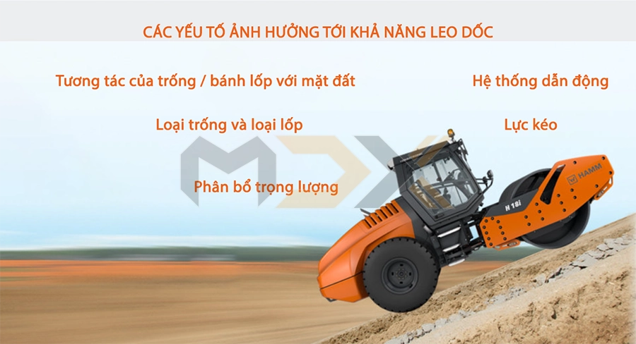
Reduced tyre pressure can increase the hill climbing ability of compactors.
- Interaction of drum/wheel to ground: Spacing surface and force. Ground characteristics.
- Weight distribution: Machine weight and weight distribution.
- Drum and wheel type: Smooth drum or padfoot drum. Diamond, tractor or EM profile. With/without drum drive.
- Drive unit: Diesel engine / axle drive. Hydraulic.
- Traction: Differential type (limited slip). Hydraulic. ASC
TYPES OF OPERATOR PLATFORM
The machines or model series can be fitted with various types of operator platform. Types of operator platform:
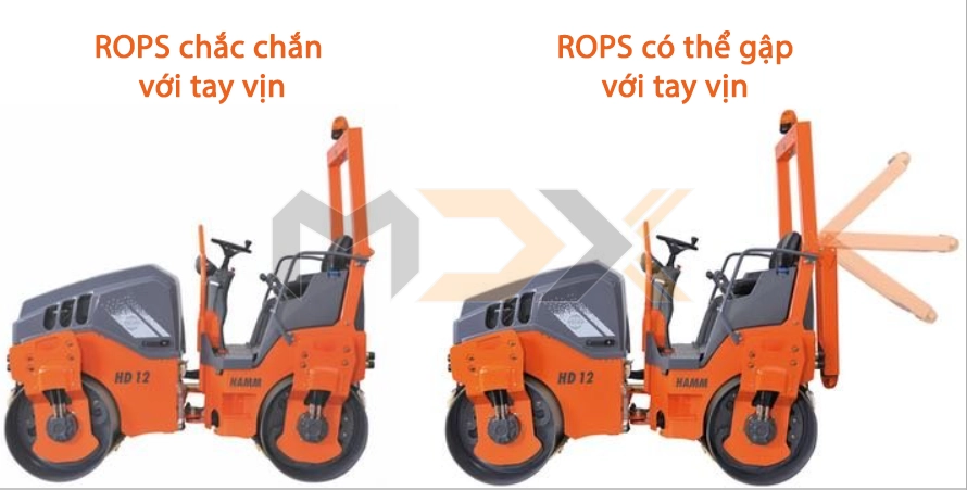
- Handrails: Handrails for safe climbing onto the operator platform. The operator is not protected by any safety equipment (no ROPS/protective roof).
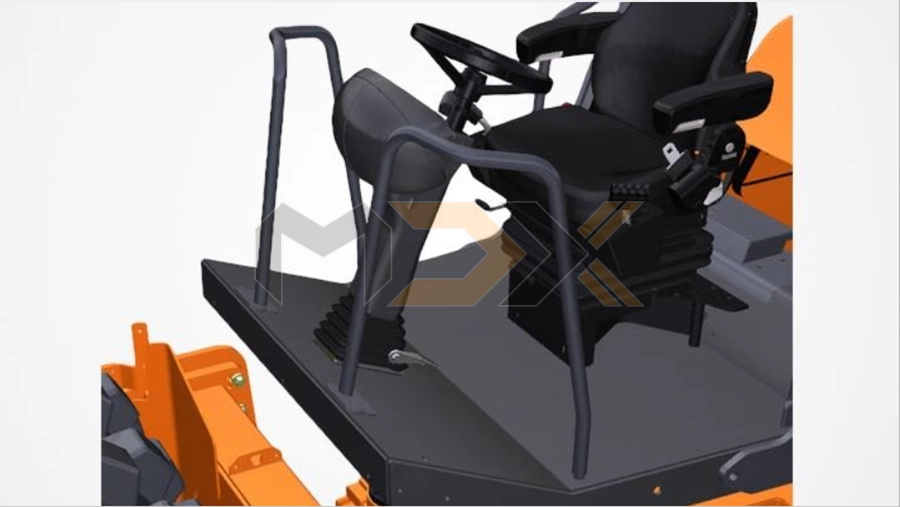
- ROPS: Safety equipment for the operator, comprised of reinforcing elements.
- Cabin: có hai loại là ROPS không được tích hợp vào cấu trúc của cabin và ROPS được tích hợp vào cấu trúc của cabin.
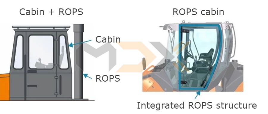
ROPS is not integrated into the structure of the cabin (left) - ROPS is integrated into the structure of the cabin (right)
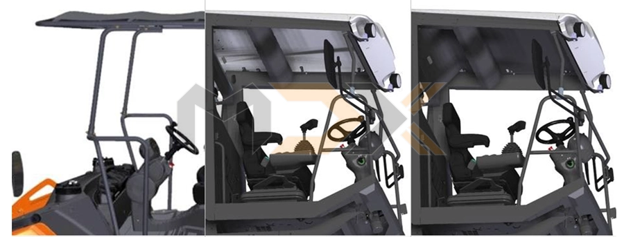
Attachments
- Plastic tarpaulin: Plastic roof mounted on handrails to protect against rain and sun.
- Protective roof, plastic: Roof structure installed on ROPS of open operator’s platform. Structure is made of hard plastic. To protect against weather influences such as the sun (UV radiation) and rain.
- Protective roof, plastic with integrated FOPS (Level 1): Roof structure installed on ROPS of open operator’s platform. Structure is made of hard plastic and metal (steel sheet). To protect against falling objects.