INTRODUCTION TO THE MULTI-POINT SENSOR SYSTEM INSTALLED ON VOGELE ASPHALT PAVERS
In asphalt paving, three factors are always prioritized: structure, smoothness, and surface texture. Among these, the smoothness of the paved surface is clearly specified in TCVN 8864: 2011 and TCVN 8865: 2011. To achieve smoothness according to TCVN or higher standards for roads requiring high flatness such as F1 racetracks, highways, airports, etc., supporting technology is an indispensable factor. The multi-point sensor system (optional) on Vogele pavers from the "dash 2" generation onwards is an extremely optimal support technology to obtain a flat paved surface with the lowest cost and construction time.

 |
This technology has been applied worldwide for a long time, and it has been used as a standard tool in hot-mix asphalt paving for roads with high flatness requirements. |
WHAT DOES THE MULTI-POINT SENSOR SYSTEM INCLUDE?
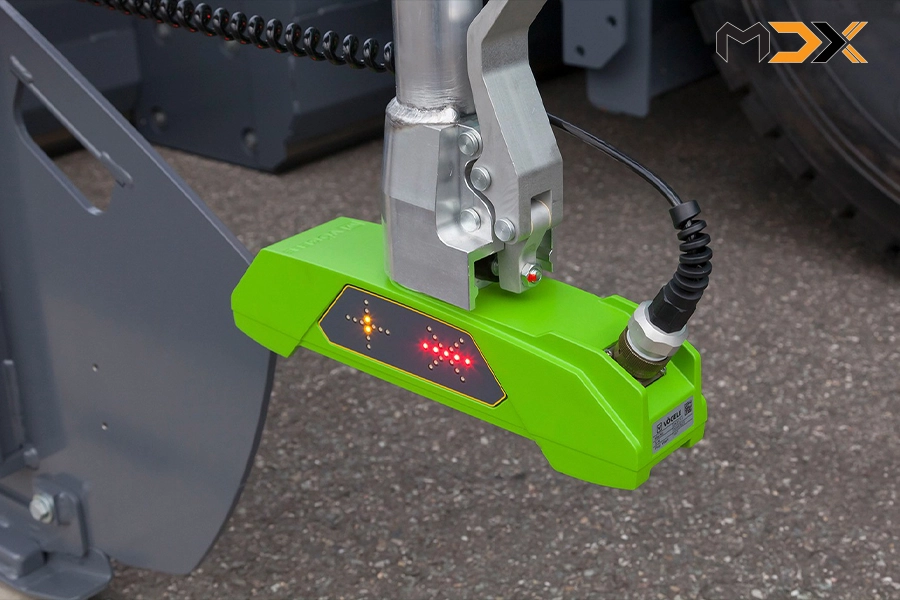
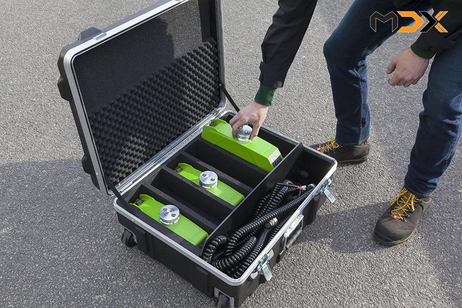
The multi-point sensor system consists of 3 ultrasonic sensors, a central processing unit, a solid aluminum support frame, and a set of connecting cables. All of this is protected in a very aesthetically pleasing and professional iron transport case.
 |
 |
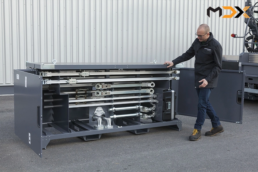 |
| Central processing unit | 3 ultrasonic sensors | Solid aluminum support frame and wiring harness |
OPERATING PRINCIPLE OF THE MULTI-POINT SENSOR SYSTEM
 |
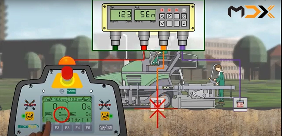
Three ultrasonic sensors of the multi-point sensor system are installed at the front, middle, and rear of the screed. - The front sensor typically measures the height of the unpaved base or the adjacent reference layer. - The middle sensor measures the height of the reference layer directly at the paving track. - The rear sensor typically measures the height of the finished paved surface. Before operation, these three sensors are set to a standard value of 0. This means that although the actual heights at these three points are different, they are brought to a standard value. During operation, the ultrasonic sensors measure the variations in the reference surface and average these values. During operation, the multi-point sensor continuously retrieves the varying values from these three ultrasonic sensors and sends them to the central processing unit. The average value of the three sensors is then used to control the screed's upward or downward movement according to the changes in the reference surface. |
ADVANTAGES OF THE MULTI-POINT SENSOR SYSTEM
 |
 |
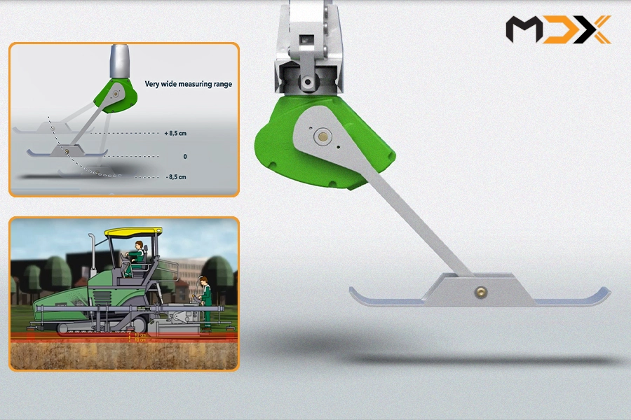
| If using a short ski plate (e.g., 20cm) on an uneven reference surface (as shown in the figure), the paved surface behind the screed will also be uneven like the reference surface. However, if using a longer ski plate (e.g., 1m or 2m), the paved surface behind the screed will be significantly flatter than the reference surface. | The multi-point sensor simulates a ski plate, and the "length" of the multi-point sensor can be flexibly changed from 5-13m. Each individual ultrasonic sensor (of the multi-point set) can be moved along the length of the support frame to achieve the optimal working length depending on the specific site conditions. The commonly used length for the multi-point sensor is 9m. |
 |
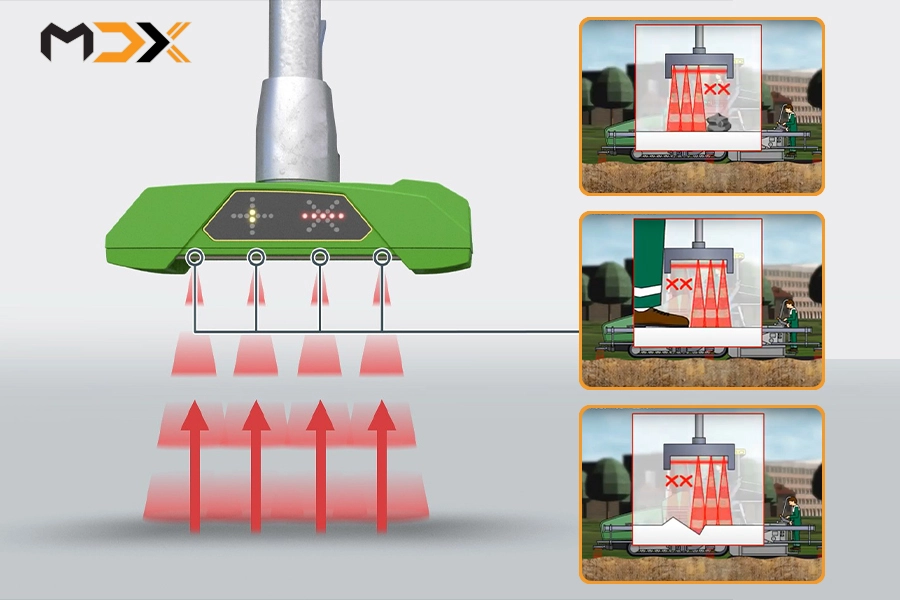 |
| With the multi-point sensor, the working range (measurable range) is ±10 cm relative to the reference plane, which is greater than the working range of the ski plate (±8.5 cm). This means that measured values greater than or less than 10 cm will not be recorded or calculated by the multi-point sensor. | In addition to the measurable range, each sensor (within the multi-point sensor set) operates on the principle of eliminating bumps, dips, and unusual obstacles on the surface, similar to the operating principle of the 5-eye ultrasonic sensor. |
|
By eliminating unusual bumps and dips on the reference surface (such as pebbles, footprints, etc.) from the measurement and averaging the remaining values, the multi-point sensor ensures that it always uses accurate data to control the screed, something that a single ultrasonic sensor or ski plate cannot do. The multi-point sensor always uses the average value of the three ultrasonic sensors to adjust the screed, so there is no need to create another reference surface such as a stringline. This saves a lot of time and cost for staking, surveying, and stringline setup. |
|
TECHNICAL INSTRUCTIONS FOR INSTALLATION AND SETUP OF THE MULTI-POINT SENSOR SYSTEM
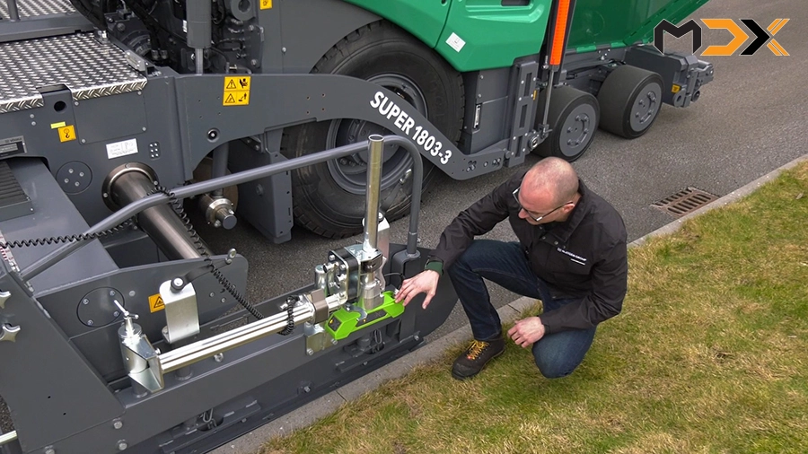
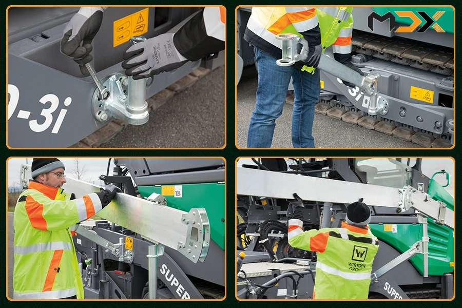
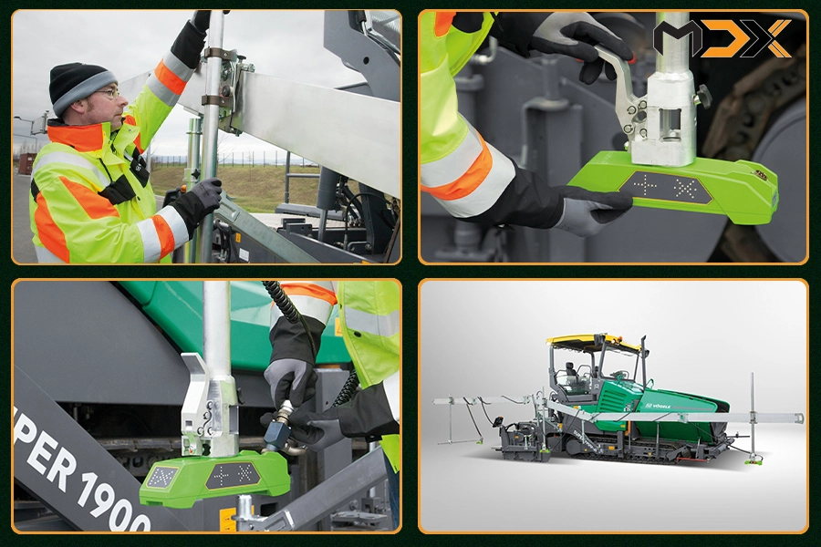
| Installing the multi-point sensor system is quite simple, almost like a child's toy. The installation process is very quick thanks to the robust and intelligent joints and clamps. The complete installation time for the multi-point sensor system is approximately 7 minutes. The sensors are automatically recognized and their order is displayed on the control screen of the central processing unit. | |
 |
 |
 |
 |
|
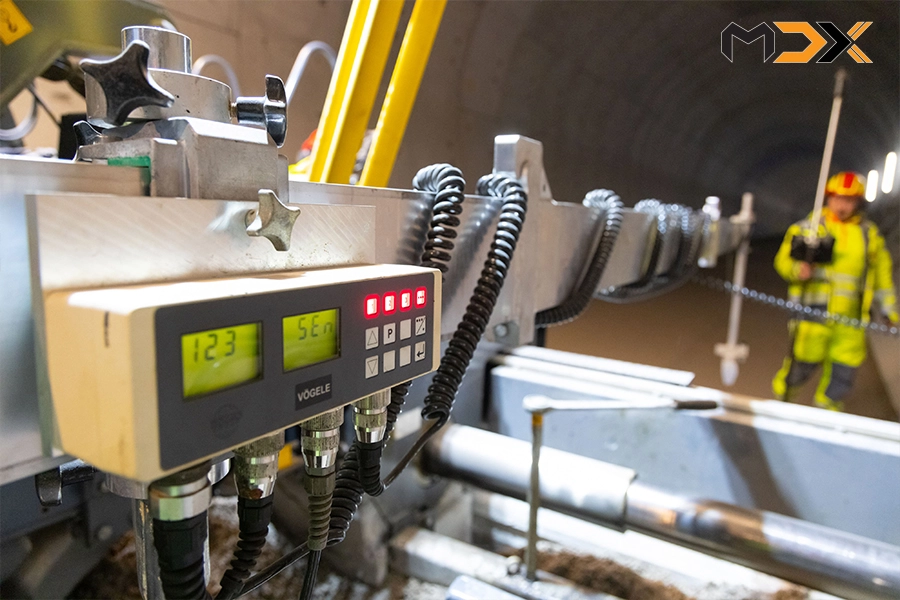
Sensor setup: Setting up the sensor only involves confirming the sensor type during the initial installation. This is done simply by pressing the Enter button for confirmation on the central controller. Zeroing the sensors: Before operation, the sensors are set to a measurement value of 0 according to their respective positions on the reference surface (all 3 sensors are set to 0 even though they are at 3 different positions with different heights) by pressing the F1 button on the control panel. |
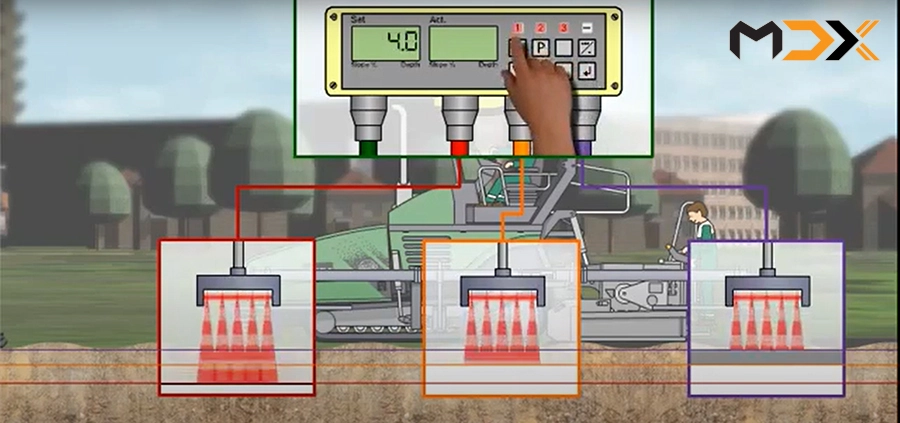
Setting the working range: In addition, the ultrasonic sensor allows for setting the working range (normally ±10 cm) via the increase/decrease buttons on the central controller. Displaying the set value: This set value is clearly displayed on the screen. The set working range is the upper and lower limit value that the central controller accepts for calculation and screed control. Values outside this working range will not be recorded, are considered incorrect values, and are eliminated from the measurement. |
HOW TO ESTABLISH A REFERENCE FOR THE MULTI-POINT SENSOR
There are two ways to establish a reference for the multi-point sensor system:
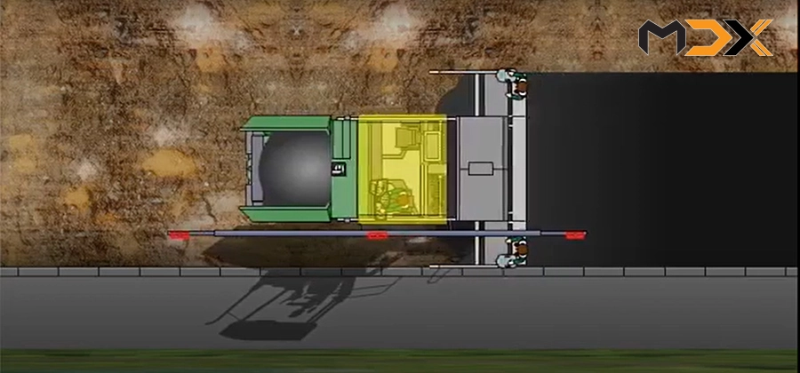 |
Method 1: Referencing within the paved area. This method is used when paving a wide lane and there is no suitable reference surface alongside. In this case, the multi-point sensor is mounted on the screed's lifting cylinders, close to the side of the paver. The front and middle sensors will then take the value of the unpaved base, while the rear sensor takes the value of the freshly paved layer. With this referencing method, the reference standard is the freshly paved surface behind the screed. |
 |
|
|
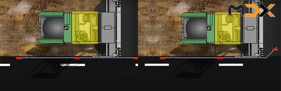
Method 2: Referencing outside the paved area. This method offers advantages and is used when the paving width is not large and there is a suitable reference surface alongside. In this case, the multi-point sensor is mounted along the side plate of the screed and references the surface outside the paving area, which could be a curb or a previously paved lane. The front and middle sensors can then take the value of the previously paved layer alongside, while the rear sensor can take the value of the freshly paved layer or the previously paved layer alongside. Furthermore, the front and rear sensors can be rotated 90 degrees or adjusted back and forth by 1.5m. This allows for easy and accurate selection of the reference position. With this method of referencing outside the paved area, there will always be 2-3 points with standard values, resulting in the most optimally flat paved surface. |
|
APPLICATION OF MULTI-POINT SENSORS WHEN PAVING MILLED SECTIONS
 |
 |
| With milled sections, the multi-point sensor automatically adjusts the height and screed angle for optimal joint creation without manual intervention. When paving milled sections, the front sensor is adjusted backward to be positioned just in front of the crawler tracks. | |