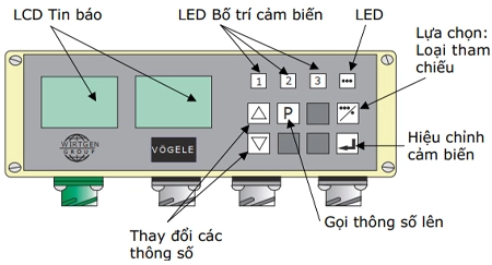
AUTOMATIC GRADE AND SLOPE CONTROL WITH NIVELTRONIC
Niveltronic is the automatic grade and slope control system researched and developed by Vogele. It includes two versions: Niveltronic Basic and Niveltronic Plus, both designed with an operator-centric focus. This is reflected in the simple, user-friendly operation, with all settings adjusted directly on the screed console. To learn more about this system, we invite you to read the following article!
SUMMARY
| 1 | Automatic Grade and Slope Control with Niveltronic | 2 | Basic Operating Principles |
| 3 | Introduction to Sensor Types |
1. AUTOMATIC GRADE AND SLOPE CONTROL WITH NIVELTRONIC
Niveltronic is the automatic grade and slope control system researched and developed by Vogele. It includes two versions:
Niveltronic Basic
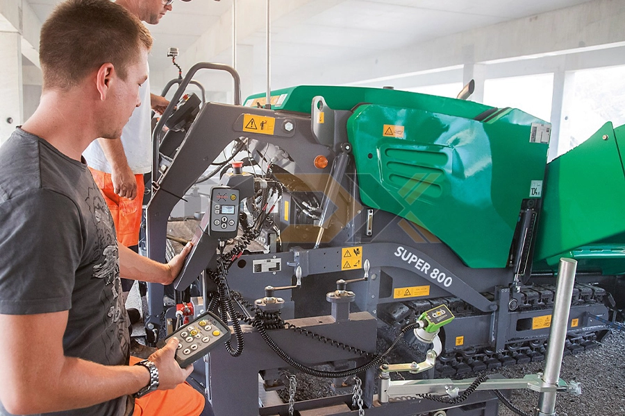 |
Niveltronic Basic, the automatic grade and slope control system, was developed for perfect compatibility with the ErgoBasic operating system. Seamlessly integrated into the machine's control system, Niveltronic Basic offers simplicity and intuitive operation, making it easy to use and accurate, even for novice operators. This system supports the Classic Line pavers in achieving accurate paving and leveling on any surface. Niveltronic Basic offers a wide variety of sensors, from mechanical to ultrasonic, meeting the diverse needs of the machine. Each side of the screed is controlled by a separate Niveltronic Basic remote control unit, compact and robust, with all necessary functions for precise grade and slope control. |
Niveltronic Plus
 |
 |
|
The Niveltronic Plus automatic grade and slope control system from Vogele provides the foundation for efficient and precise asphalt paving on any base. Niveltronic is the result of many years of experience, offering the perfect solution in terms of ease of operation, quality, and reliability for all automatic grade and slope control tasks. - Sensor compatibility: Niveltronic Plus is compatible with all connected sensors, making setup particularly quick and easy for the user. - Seamless integration: It is perfectly compatible with all Vogele paver components. For example, all wiring and connections are integrated into the screed tow point and screed, virtually eliminating any damage to these components. |
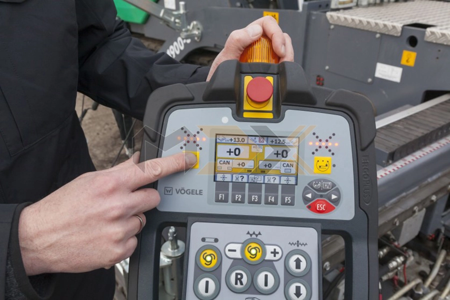
- Operator-centric design: During the development of Niveltronic Plus, the focus was placed on the operator, ensuring simple and user-friendly handling. All settings are made on the screed console. The clearly arranged controls and keys allow the screed operator to understand and safely control all main functions within a very short time. - Wide sensor selection: Vogele offers a particularly large and practical selection of sensors to allow flexible use of the Niveltronic Plus system. Whether the construction project is a parking lot, roundabout, or highway, there are suitable sensors available. |
 |
Key advantages of Niveltronic Plus: - Exclusive to Vogele: The automatic grade and slope control system is supplied directly by Vogele. - Integrated design: Wiring and connections are integrated into the screed raising/lowering cylinders and screed. - Versatile sensor options: A wide variety of sensors support the flexible use of Niveltronic Plus in all application areas. - Automatic sensor recognition: Connected sensors are automatically recognized for quick and easy setup. - User-friendly operation: Control and monitoring of all Niveltronic Plus functions are particularly easy and user-friendly. - Intuitive interface: Logical, self-explanatory symbols and neutral language support quick learning of all functions. - Seamless integration: Fully integrated into the paver's control system, Niveltronic Plus requires no additional training to operate. |
2. BASIC OPERATING PRINCIPLES
 |
|
|
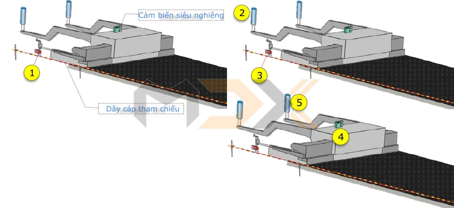
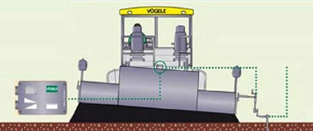
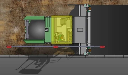
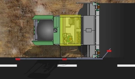
- Basic configuration: The left side uses a mechanical grade sensor, while the slope sensor maintains the slope for the paved lane. - Operating principle: When copying the reference surface, any upward or downward movement of the screed is registered by the mechanical sensor. The deviation between the set value and the actual value is immediately processed by the screed controller to ensure the paving requirements are met. This is done by the automatic grade controller. - Deviation from reference: The grade sensors [1] automatically detect the deviation from the reference. - Left-side control: The height of the sensor is adjusted by the grade cylinder [2] when any change is detected, and the sensor [3] is brought back to the correct grade as initially set. The grade cylinder on the other side is only controlled when the slope sensor [4] confirms that there is a deviation from the initially set slope value. - Right-side control: The grade cylinder [5] receives the control signal when the initially set value is reached. |
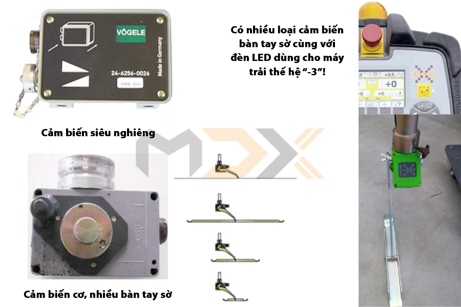
3. GIỚI THIỆU CÁC LOẠI CẢM BIẾN
 |
The term "grade" in this context means: - To level something. - To plane something. - To smooth something. - To bring something to a common standard. - To eliminate differences. |
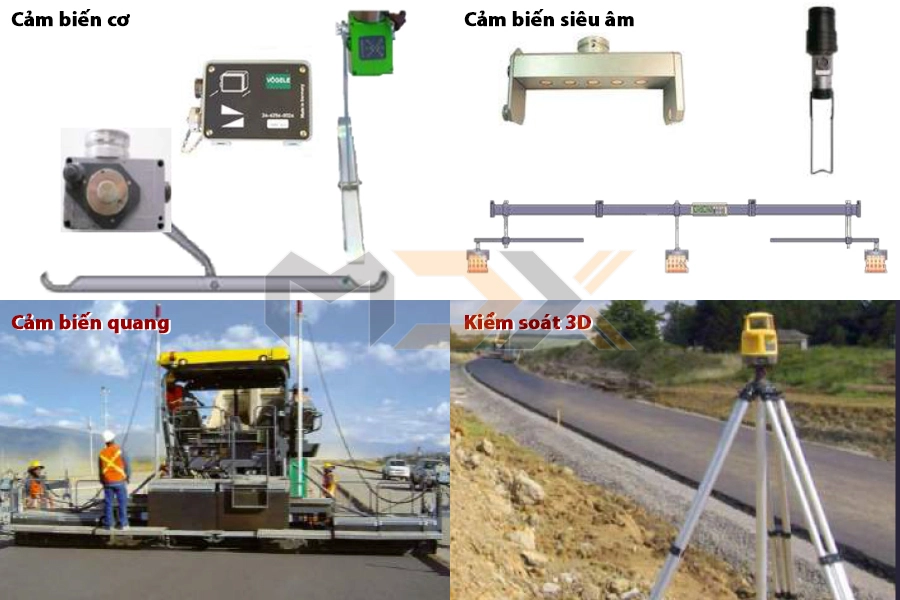
| Mechanical Sensors | |
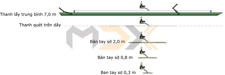 |
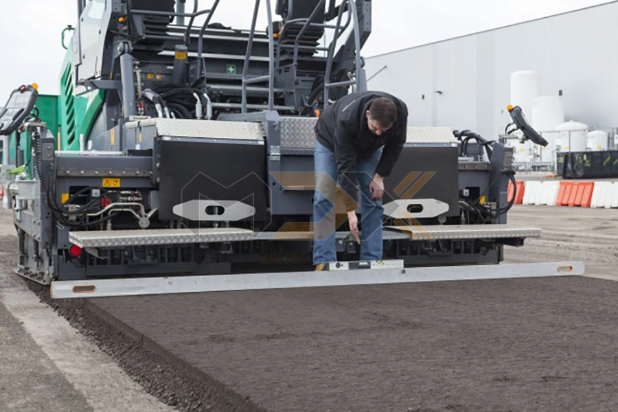
Advantages of mechanical sensors: - Robustness: Largely unaffected by external influences such as humidity, wind, and temperature. - Visible measurement: The measurement process is "visible." This means that it can be seen whether the sensor is in contact with the reference surface and also where the sensor is scanning. - Variety of ski plates: Ski plates (for ground referencing) are available in lengths of 0.3 m, 0.8 m, or 2.0 m. - Short ski plate (0.3 m): Suitable for referencing on tight bends or roundabouts (complete 1:1 copying of the reference surface). - Medium ski plates (0.8 m or 2.0 m): Recommended for dealing with small irregularities in the base. - Averaging beam: Should be used for larger irregularities. |
 |
|
 |
 |
| A slope sensor can be used in combination with one mechanical sensor. The slope sensor can also be used in combination with another grade sensor when paving with a width of no more than 6 m. The slope angle of the screed is measured by a fluid-filled sensor, which, together with a spirit level, allows the slope angle to be determined within a range of up to +/- 10%. | The slope sensor is mounted on the cross member between the two screed tow points. The illustration above is magnified. |
| Các cảm biến siêu âm, loại không cần tiếp xúc | |
 |
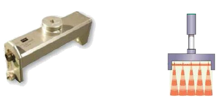 |
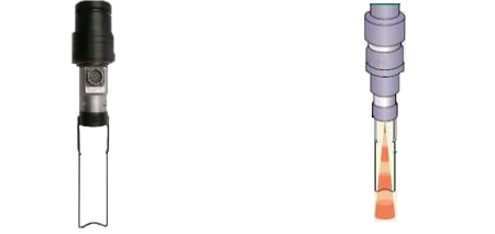
| The working principle of all ultrasonic sensors is basically the same: An ultrasonic signal is emitted, then reflected back and registered by the sensor. The time span from the emission of the signal until it is received back is used to calculate the distance to the reference being used. | |
| Multiplex Big Ski | |
 |
|
 |
 |
|
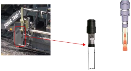
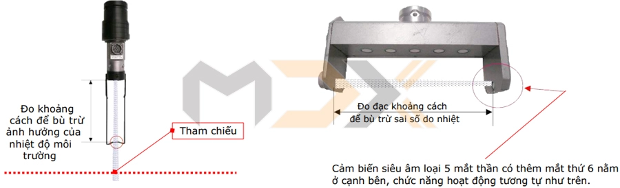
Single-eye ultrasonic sensors emit only one conical sound wave. As a result, the reference surface is copied 1:1 without averaging. This type of sensor is suitable for job sites with: - Tight bends - Winding roads with tight curves - "Hot-on-hot" or "hot-on-cold" paving of two lanes in parallel - Copying slopes, speed bumps, or similar structures |
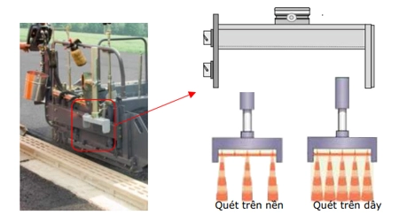
Small irregularities can be optimally compensated for by using the average value of the three best signal fields (non-contact mode). This sensor type can also be used for string line referencing. In this case, the 5-eye sensor is used (contact mode), but only the signal that detects the reference wire first is used to adjust the automatic controller. |
| Operating Principle | |
 |
|
| Nguyên lý hoạt động | ||
 |
||
|
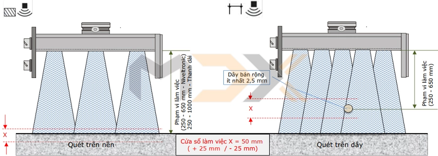
Niveltronic (Non-contact mode): - 3 sensors active. - Averaging employed. - Adjustable working window. - Adjustable sensitivity. - Position: Along the edge |
Multiplex Big-Ski Sensor (Non-contact mode): - 5 sensors active. - Averaging of 3 signals. - Adjustable working window. - (Niveltronic & beam!). - Position: Along the edge. |
Niveltronic and Multiplex Big-Ski Sensor (String line mode): - 5 sensors active. - No averaging. - Uses the first returned signal from the reference wire. - Adjustable sensitivity. - Adjustable working window. |
| Big Multiplex Ski | |
 |
 |
|
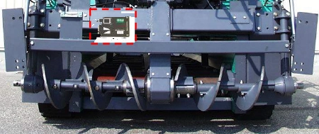
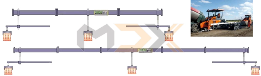
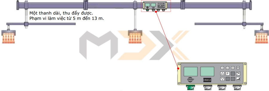
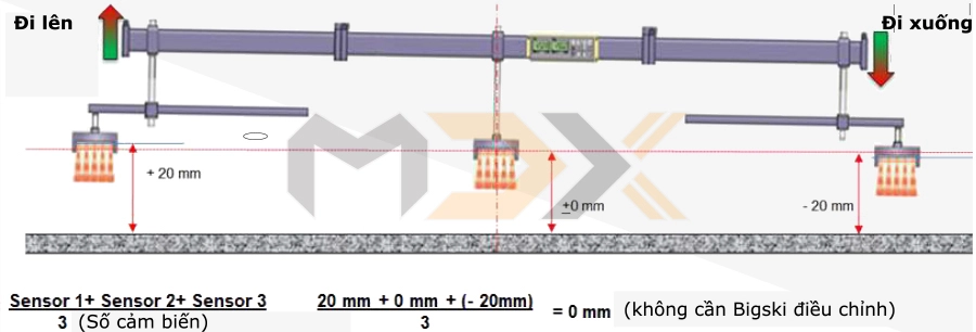
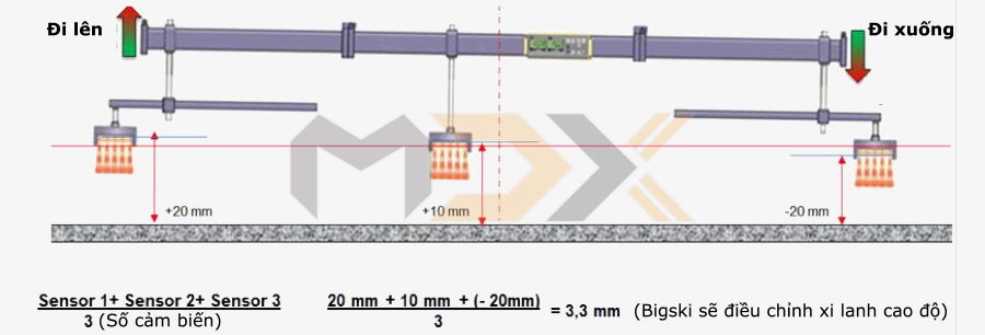
Three 5-eye ultrasonic sensors are used, each of which sends a (averaged) signal to the Niveltronic processor mounted on the beam. Each ultrasonic sensor sends its measured signal to the central processor. There, the three signals are averaged again. |
Obstacles that lie outside the permissible tolerances are eliminated and not used in the averaging calculation (e.g., boulders). Note the configurations of the multi-point sensor: - Installation with 3 ultrasonic sensors. - Beam with only 1 ultrasonic sensor. |
 |
|
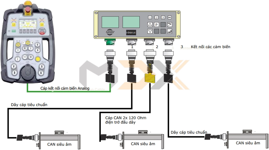
| Connections of the Multiplex Big-Ski Sensor System | |
 |
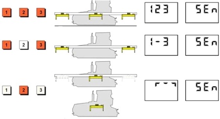 |
| Central processor of the Big Multiplex Ski system | Sensor Recognition: The sensor station used is identified by the LED signal. Sensor configurations or sensor errors are displayed on the LCD screen. |
 |
 |
|
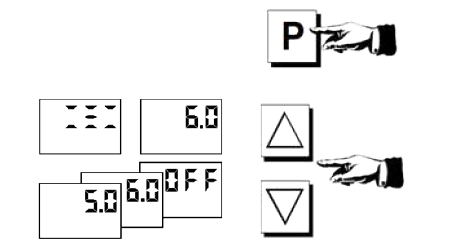
Calling up parameters (Working window) - Call up "Working window". The value corresponds to the permissible measuring range of the sensors. E.g.: 6 = +/- 3 cm. - Change (each press = 1 cm, from 4 to 20) or do not use range (greater than 20.0 = OFF). |
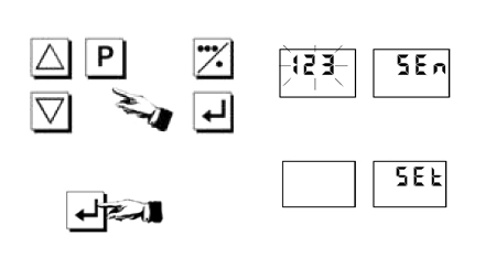
Sensor information: When the multi-point sensor is connected for the first time or when the combination of sensors is changed, sensor recognition must be carried out again. The displayed numerical values will flash before confirmation. After confirmation (press any key), the display remains ON. Calibrating values: The sensors must be calibrated before starting for the first time or when there are changes in the sensor settings. Once calibrated, the word SET will appear on the display. |
 |
 |
| Scanning within the paved area | Scanning outside the paved area |
 |
 |
| Sensor Installation | |
 |
 |
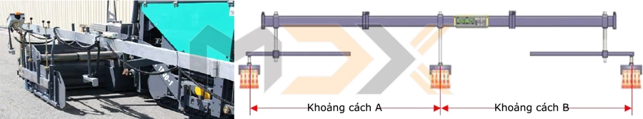
| Installation principle #1: "Distance A" must be equal to "Distance B"! |
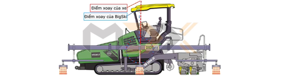
Installation principle #2: The position of the pivot point on the Big-Ski sensor beam must be aligned with the pivot point of the paver. Explanation: The pivot point of the tractor unit must be approximately aligned with the pivot point of the Big-Ski sensor beam. This position has a considerable influence on the functionality of the system, for example, when paving or when referencing at the edge. |
| The center sensor is "mounted in the center" | The center sensor is "not mounted in the center" |
 |
 |
| When the system is working within the working window, the up and down movements of the Big-Ski beam will not affect the height control signal because the sensor is mounted at the center. | Because the sensor is not mounted at the center, errors in the height control signal can occur when the Big-Ski beam moves up and down during paving. |
| Operating tips - Paving towards the joint | Tips for paving - Paving tight curves |
 |
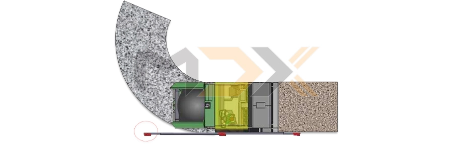 |
| Example: Paving towards a bridge edge or a milled edge. | When paving through curves, the leading sensor of the system may leave the optimal reference position, which will lead to an incorrect measurement. |
|
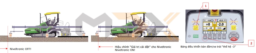
Procedure (using the "Big-Ski" system on the left side): - Deactivate Niveltronic: Before the first sensor reaches the edge, deactivate the Niveltronic system on the screed [1]. - Confirm new reference: As soon as the first sensor is over the joint, confirm the new reference surface by pressing "F1" [2] and then reactivate the Niveltronic system by pressing [1] again. This adjustment can be made without stopping paving! Note: No further settings need to be made on the Big-Ski central controller if its working window is set to "OFF". |
|
| Tips for paving - Paving on a slope (uphill or downhill) |
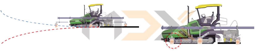
When paving uphill or downhill, the leading sensor may deliver incorrect signals or deviate from the correct reference. This can lead to faulty control signals or even to system interruption and automatic shutdown. Solution for both cases: In both cases, the leading sensor should be mounted next to the front edge of the crawler track or the front axle for tracked pavers. |
 |
|
| Non-contacting optical sensors (laser) | |
| Operating Principle | |
 |
 |
|
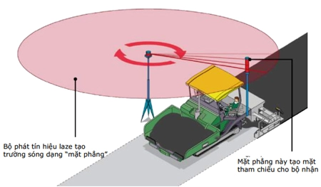
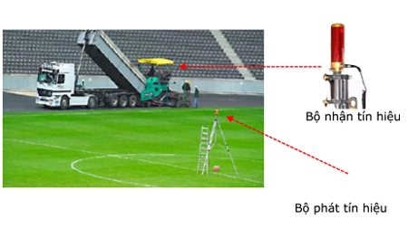
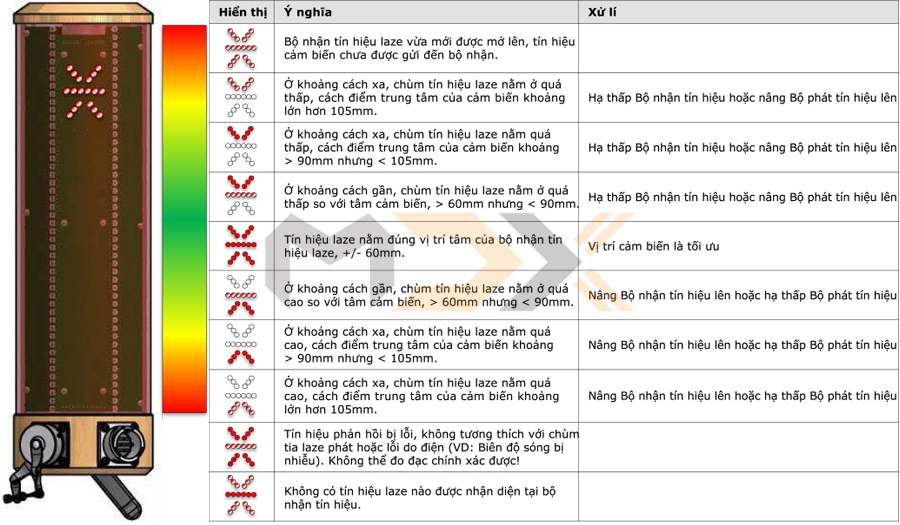
Compared to ultrasonic sensors, optical sensors work with laser beams. Advantages: - Signal is not affected by wind or temperature. - Large laser beam operating range. The laser transmitter generates a "plane-shaped" wave field thanks to the rotating laser beam. This plane is registered by the receiver (mounted on the paver). |
The use of a laser receiver is necessary when paving large areas with constant transverse and longitudinal slopes, such as sports fields, parking lots, or storage areas. Re-adjustment of the receiver's mast height is not required during the paving process thanks to the sensor's particularly large measuring range. Note: Fog, rain, and reflecting surfaces on surrounding buildings can affect the quality of the laser signal. |
 |
|
| Laser Receiver LS300 | |
| 3D sensors with the Navitronic Plus system | |
| Operating Principle | 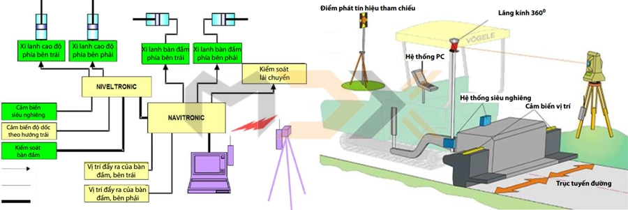 |
| Navitronic Plus is a 3D control system for stringless referencing. Control is implemented by means of an external computer connected to the paver via a common interface. | |