BASIC KNOWLEDGE ABOUT ASPHALT MIXING PLANT
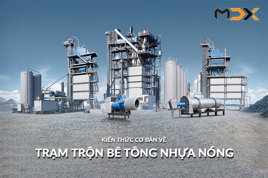
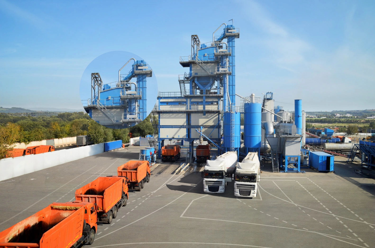
An asphalt mixing plant is a complex system designed to mix and heat aggregates (mineral stones, rock dust, filler, and other additives) with bitumen in specific proportions to produce a homogeneous hot mix asphalt (HMA) at the required temperature. This intricate process is managed through a central control system, with production capacities ranging from 80 to 320 tons per hour. This article provides a comprehensive overview of asphalt mixing plants.
BASIC COMPONENTS OF ASPHALT
Hot mix asphalt (HMA) is a composite material comprised of three primary components: aggregates (crushed stone, gravel, sand), filler (mineral powder), and asphalt binder (bitumen). The proportion of each component is precisely determined by the mix design, ensuring the mechanical properties of the HMA meet the specific engineering requirements of the project.
| Aggregates / Stones / Minerals | Filler / Stone Powder | Bitum |
 |
 |
 |
|
The base layer of hot mix asphalt (HMA) is constructed using aggregates, typically comprising crushed stone, gravel, and sand with varying particle sizes. This gradation of aggregates creates a robust load-bearing structure, ensuring stability and load-carrying capacity for the pavement. |
Filler (mineral powder) plays a crucial role in hot mix asphalt (HMA) by filling the voids between aggregate particles. This action increases the cohesiveness and density of the asphalt mix. There are two primary types of filler used in HMA production: - Reclaimed Filler: This is derived from dust generated during the HMA production process, typically collected by the dust collection system. It is then stored in a dedicated silo for later use. - Imported Filler: This type of filler is sourced from external suppliers and meets specific quality standards for mineral composition and particle size. It is stored in separate, designated silos. |
Asphalt binder (bitumen) is a viscous, organic liquid derived from petroleum. In hot mix asphalt (HMA) production, the binder acts as the glue, coating and binding the aggregate particles and filler together to form a cohesive mass. To maintain its workable viscosity, asphalt binder is typically transported and stored at temperatures around 160°C (320°F) in specialized, heated tanks equipped with temperature maintenance systems. |
OVERVIEW OF HOT ASPHALT MIXING PLANT
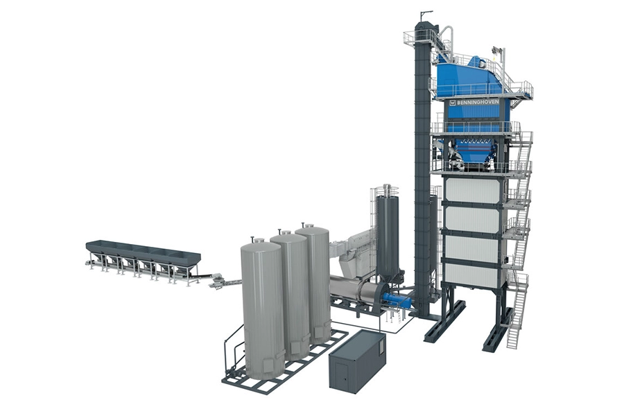
To achieve a homogeneous hot mix asphalt (HMA) blend, each of the three primary components—aggregates, filler, and asphalt binder—undergoes separate processing and handling within the asphalt mixing plant. Each component follows a distinct path through specialized equipment designed for specific functions, ensuring the final product meets stringent quality standards.
Aggregate Processing Line
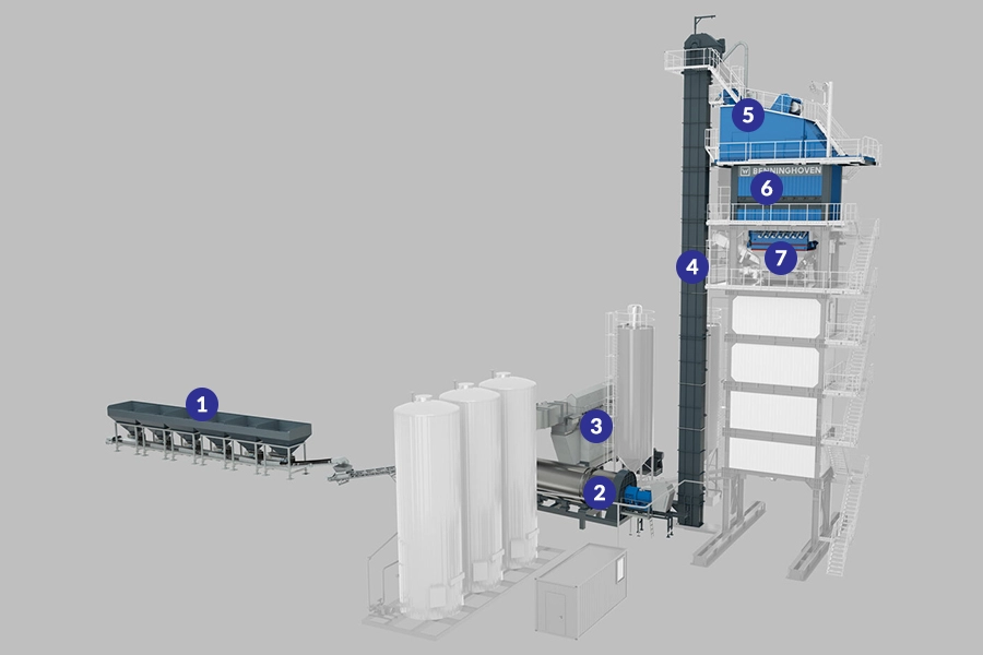
| 1. Cold Feed System | 2. Drying Drum and Burner | 3. Hệ thống gom bụi |
|
Receiving aggregates (crushed stone, gravel, sand) from various sources. Storing aggregates by type and size in feed bins. Performing initial proportioning of aggregates according to the mix design using weigh hoppers. |
Drying the moist aggregates using a rotary drying drum. Heating the aggregates to the required temperature (around 160°C) using a burner fueled by diesel, fuel oil, or gas. A draft fan creates negative pressure (50-100 Pa) inside the drying drum to aid in the drying process and dust extraction. |
Maintaining low pressure (50-100 Pa) inside the drying drum by the dust collection system fan, exhaust fan. Extracting fine dust generated during the drying process from the drying drum. Collecting dust for reuse as reclaimed filler or disposing of it according to environmental regulations. |
| 4. Hot lifting belt | 5. Screening machine | 6. Hot hopper stage |
|
Transport hot aggregate from the drying drum to the mixing tower. The conveyor belt is made of heat-resistant material to ensure safety and efficiency of transportation. |
Classify hot aggregate into different particle sizes by vibrating screen. Each particle size will be transferred to the corresponding hot hopper. |
Temporary storage of hot aggregates classified by grain size. Feed aggregates to the mineral weighing hopper as required by the control system. |
| 7. Mineral weighing funnel | Accurately quantify the mass of each type of aggregate from the hot hopper according to the designed mix. The scale is automatically controlled to ensure high accuracy and stability for each batch. | |
Filler processing line
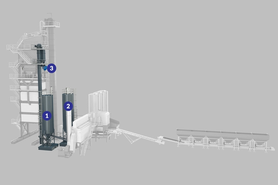
| 1. Recycled filler silo | 2. Imported filler silo | 3. Filler weighing sheet |
| The filler is recovered during dust collection and stored here. | Purchased filler can be stored in a second silo. | The filler is weighed precisely according to the formula. |
Bitumen processing line
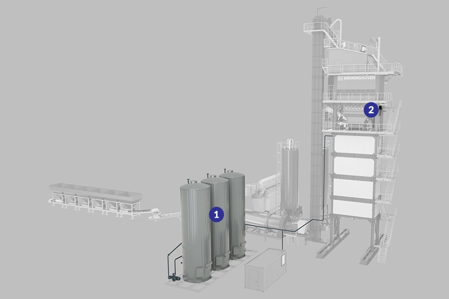
| 1. Bitumen tanks | 2. Bitumen weighing hopper |
| Bitumen is distributed at 160°C, contained in heated bitumen tanks and maintained at temperature. | Bitumen is weighed accurately according to the formula |
Asphalt processing line
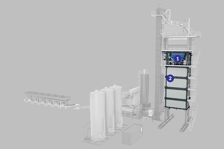
| 1. Weighing and mixing stage | 2. Silo containing mixing materials |
| After weighing, all ingredients are fed into the mixer to produce a homogeneous mixture. The corresponding mixing cycle is 45 seconds. | Asphalt is stored in mixing silos until it is ready for shipment. |
Discontinuous asphalt production process
Continuous and batch asphalt production
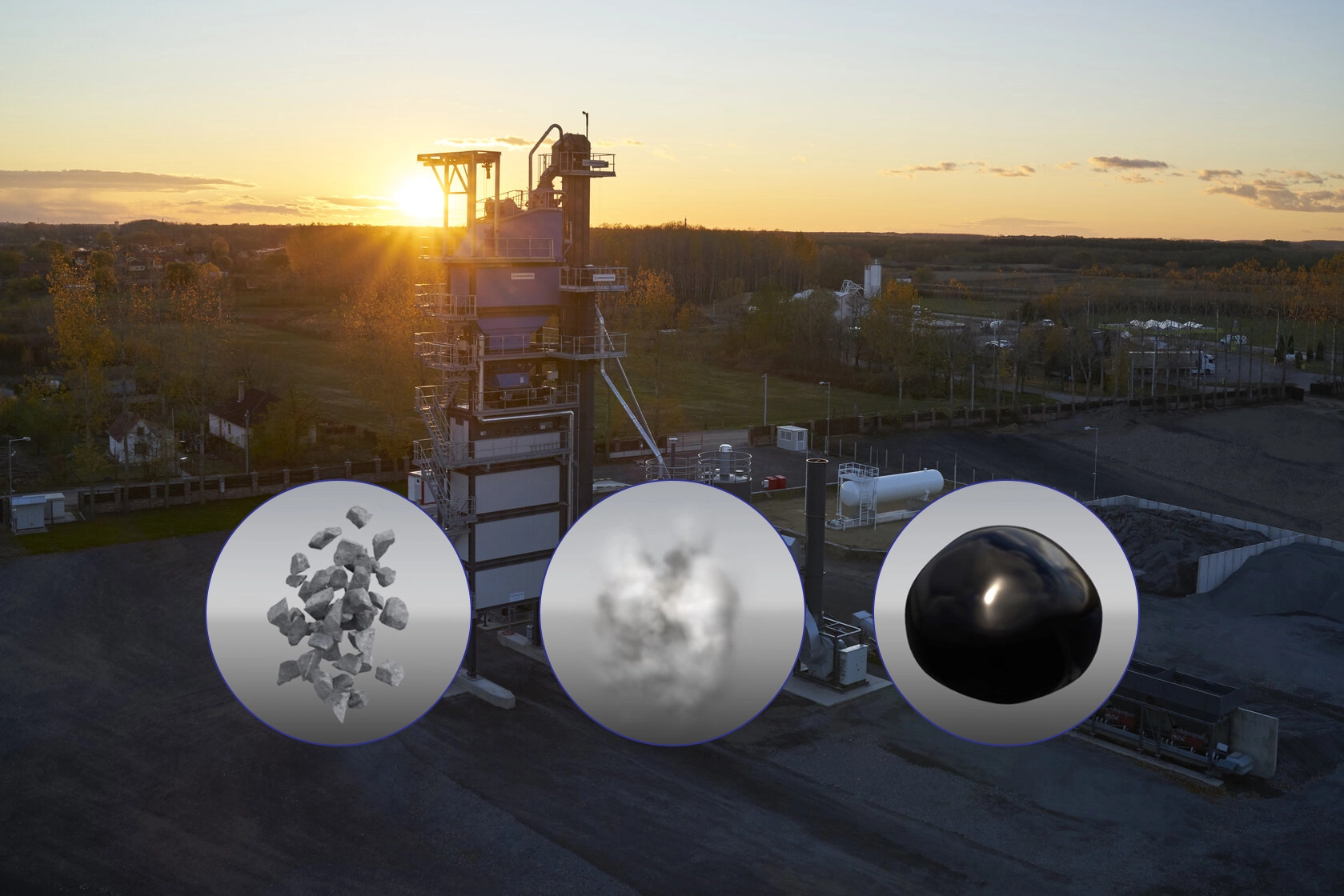
In the batch production process, the components of hot asphalt concrete (aggregates, asphalt, additives) are precisely measured according to the design formula and fed into the mixing chamber in separate batches. This method allows flexible adjustment of asphalt concrete mix proportions between batches, meeting the diverse requirements of each layer of pavement structure. The advantage of batch production is the ability to precisely control the quantity of materials and mixing time, thereby improving the uniform quality of the finished asphalt concrete mixture. This is also the operating principle of BENNINGHOVEN asphalt concrete mixing stations.
In contrast to batch production, the continuous production process takes place without stopping, materials are fed and mixed continuously at a stable speed. The advantage of this method is high productivity, suitable for large-scale projects with the need for uniform asphalt concrete. However, continuous production is limited in the ability to adjust the mix proportions when it is necessary to change the type of asphalt concrete.
AGGREGATE PROCESSING LINE
Cold feeder
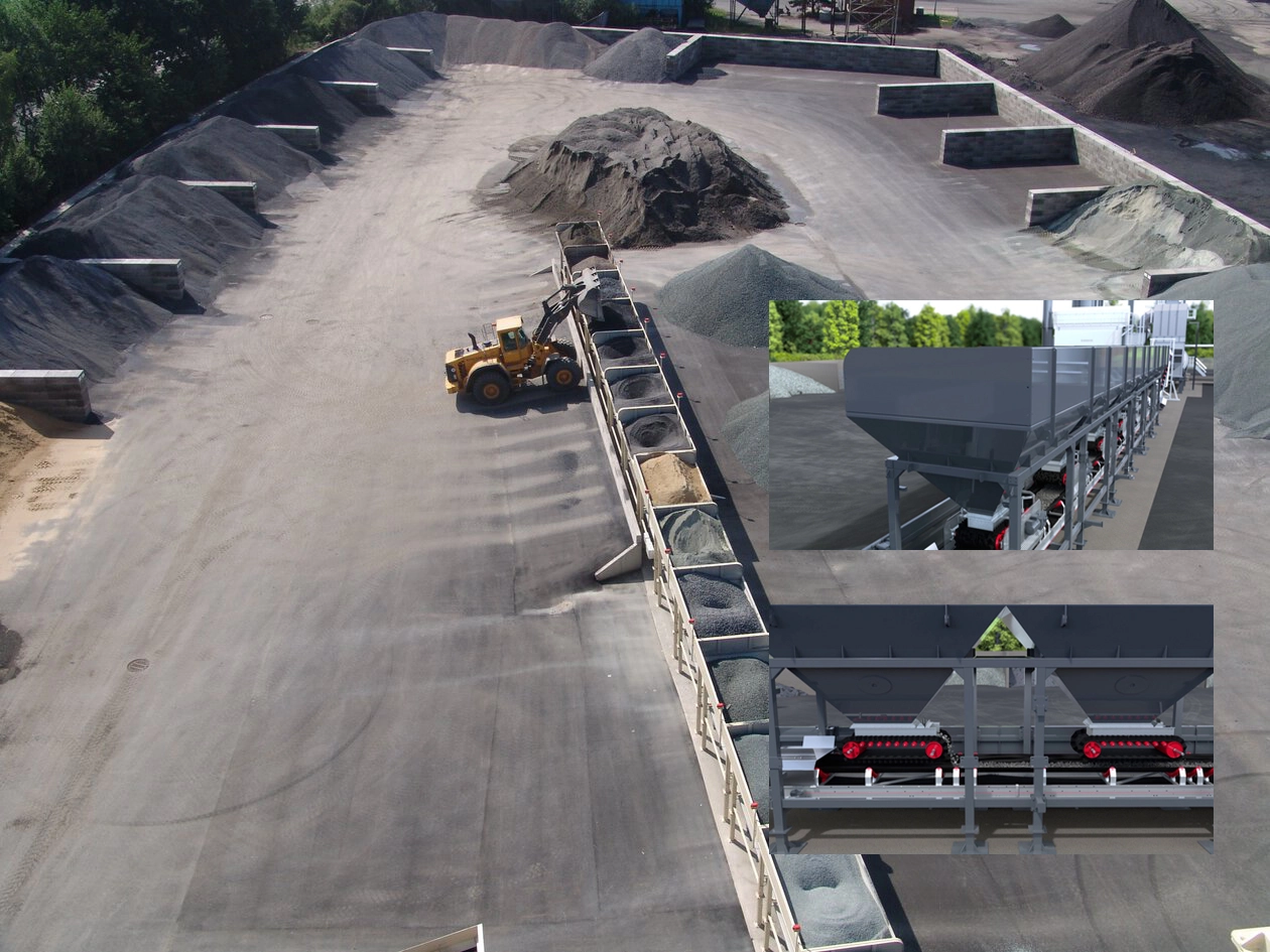
- Aggregates are stored in separate hoppers according to particle size.
- Depending on the type of mixing plant and customer requirements, the amount of feed can be changed.
- Based on the cold feed formula, minerals are dosed through the feed belts.
- Aggregates are fed into the drying drum through the assembly conveyor, inclined conveyor and sliding conveyor.
Drying and heating
- In the dryer, the aggregate is dried and heated by the burner.
- The burner is installed at the front of the drying drum, and the size and drying capacity can be changed like the drying drum. The BENNINGHOVEN burner can operate with different fuels.
- Due to the rotation, the material in the drying drum flows towards the flame of the burner. This principle of material transport is called the counterflow principle
Transporting materials by counter-flow principle
Structure of the dryer
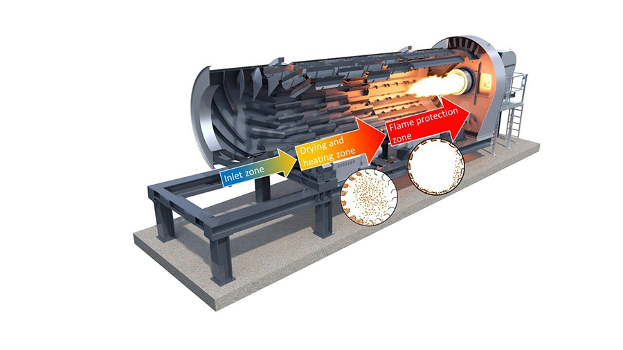
Basically, we can identify 3 zones in the dryer drum: the inlet zone, the drying and heating zone, as well as the fire protection zone. In the inlet zone, the stone is transported to the first row of pallets by means of screws. With the help of the next rows of pallets, a material barrier is created in the drying and heating zone. The material is dried and heated with hot air. In the fire protection zone, fire protection is installed that prevents the aggregates from being destroyed by fire and protects the drum from hot fire.
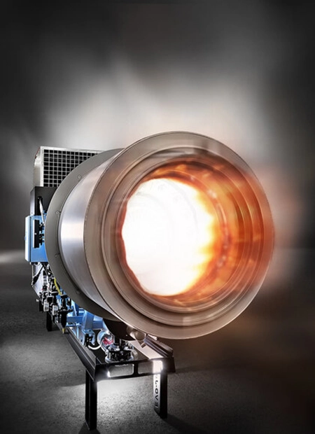 |
- Combined burner with fuel change at the push of a button - Available fuels (combinable): oil, solid oil, lignite (dust coal), natural gas, liquid gas. - Note: Lignite always requires a second fuel. - High efficiency (frequency control) - Minimized polluting emissions thanks to modern control technology - Compact design - Easy maintenance - Good retrofit options for both in-house and third-party batching plants. |
Dust collection system
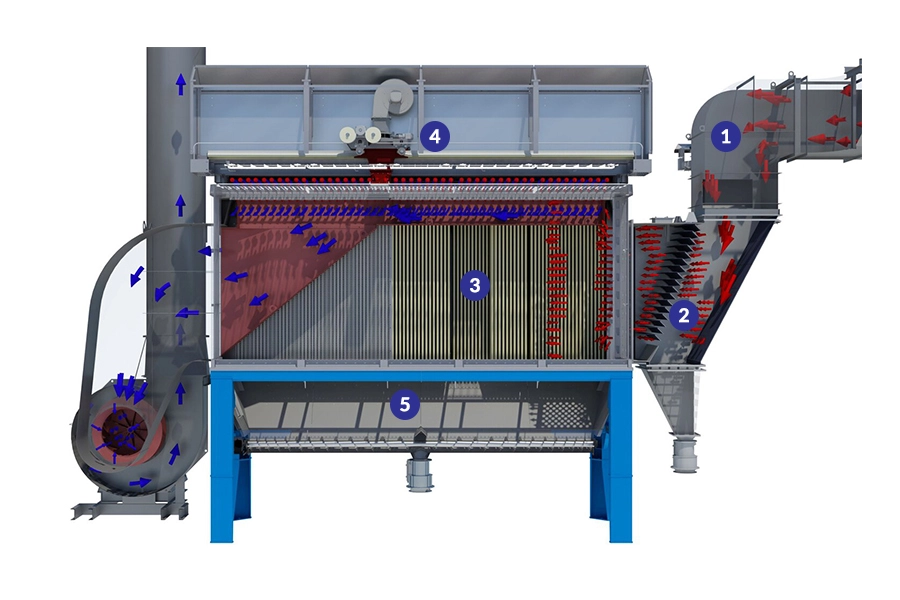
Fine dust generated during the drying process will be collected in the dust collection system. It is filtered and treated as a regenerated filler, then stored in the regenerated filler silos.
| 1. Raw air duct | 2. Preliminary separator | 3. Filtration stage |
| Due to the low pressure in the drying drum, the fine particles are transferred through the raw air duct into the dust collection system. | Here, the separation of larger particles is done on the principle of deflection. The system is designed with several deflection points using gravity and inertia. The material separated here is called coarse filler and is conveyed to the hot elevator belt through coarse filler screws. | The filter bags made of fine needle felt filter out remaining fine particles from the raw gas. They are gently cleaned with low pressure purge air, ensuring that they maintain maximum efficiency. The bags are durable and can be easily inspected and replaced from above without the need for tools. |
| 4. Air sweeping system with air blower for cleaning | 5. Dust collection trough | |
| The air sweeping system with air blowers ensures the cleaning of the filter bags. They move in stages depending on the filter load. The air blowers for cleaning generate the previously mentioned low pressure cleaning air, which is necessary to clean the filter bags. | The separated fine filler falls into a collection trough and is transported via fine filler screws and filler elevators into the regenerated filler silo. From there it is available for further production. |
Screening and separation
Hot conveyor, sieve and hot hopper process.
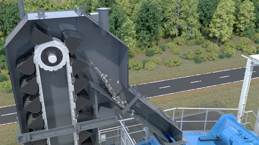
Băng nâng nóng vận chuyển đá lên điểm cao nhất của trạm trộn. Từ đó, nó đi qua một máng đến hệ thống sàng lọc. Băng nâng nóng bao gồm các thùng được gắn trên các dây chuyền kép ổn định.
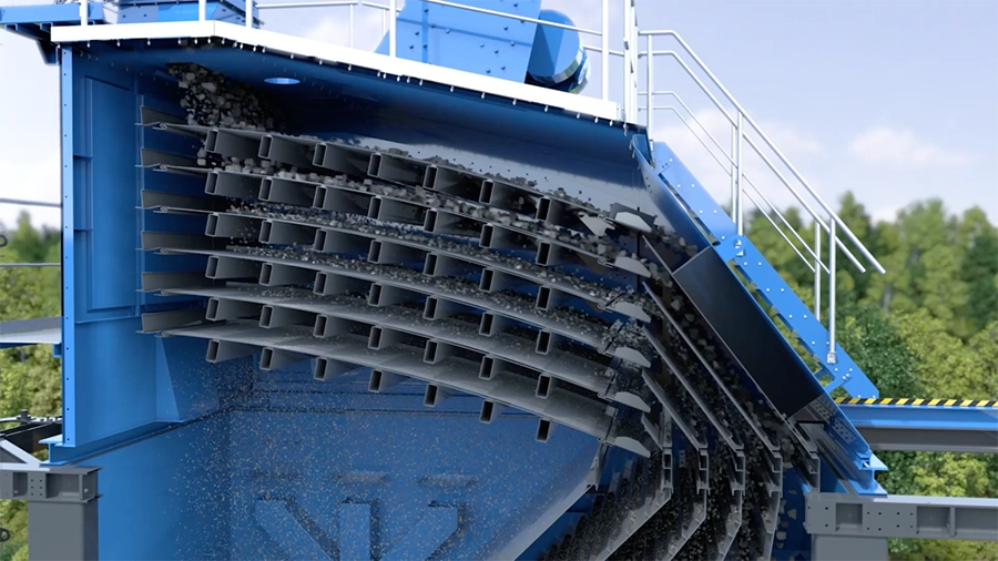
Depending on the size and type of mixing plant, the screening system is equipped with 4, 5 or 6-stage screens, which help to collect aggregates with different particle sizes.
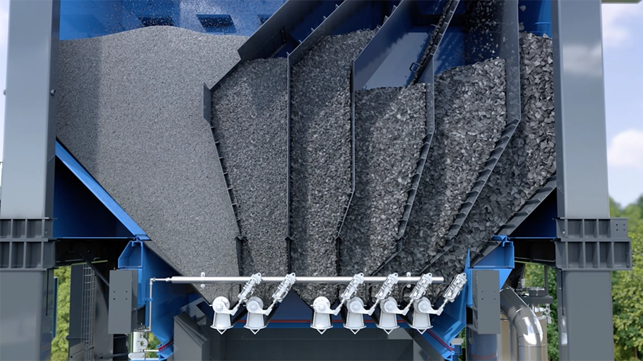
In the hot hopper stage, the aggregates are now available for further processes, completing the aggregate processing line.
FILLER PROCESSING LINE
Filler Reserve
Filler (also known as mineral powder) is an important ingredient in hot asphalt concrete, which fills the gaps between aggregate particles, increases the bonding, density and stability of the mixture. There are two main types of fillers used in hot asphalt concrete production.
- Recycled filler: Recovered from dust generated during the asphalt concrete production process, mainly from the dust collection system of the drying drum. After being recovered, the recycled filler is stored in a separate silo. The use of recycled filler contributes to environmental protection and saves production costs.
- Imported filler: Is a type of mineral powder mined and supplied from external sources, meeting technical requirements on mineral composition, particle size and other quality indicators. Imported filler is transported to the mixing station and stored in a specialized silo.
Role of filler: Fill the gaps between aggregate particles, creating a denser and more seamless asphalt concrete mixture. Enhance the bond between aggregate and asphalt, improve the durability and stability of asphalt concrete. Improve the water resistance and environmental impact resistance of asphalt concrete.
Filler content: The proportion of filler used in hot mix asphalt concrete depends on the design mix and current technical regulations.
Filler system
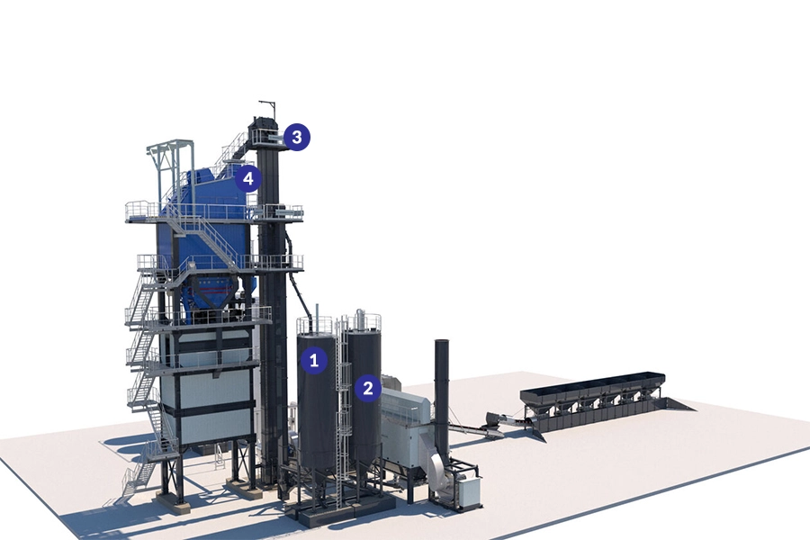
| 1. Recycled filler silo | 2. Silo containing imported filler |
|
The recycled filler collected during the dust removal process is stored in a recycled filler silo. This silo is made of solid steel plate. The legs and body of the silo are securely fastened together. Access to the silo roof is via a ladder with a guard behind.
|
 |
| The purchased filler is stored in the imported filler silo. This silo is also made of solid steel plate. The foot part is also firmly connected to the silo body. The imported filler silo can be identified by the silo lid filter. | |
| 3. Filler Lift Bandage | 4. Buffer silo |
| To introduce the filler into the mixing process, a belt elevator is required. This belt elevator transports the filler to the weighing and mixing system. Since the two types of filler (recycled filler and imported filler) must be transported and stored separately, a double belt elevator is required. |
From the double filler elevator, the filler types are transported separately, each type being fed into a separate buffer silo. The filler is temporarily stored in the buffer silo. This makes it available for subsequent processes. The filler is dosed into the filler scale using a separate dosing screw for each type. The filler transport process is completed here.
|
BITUMEN PROCESSING LINE
Bitumen storage
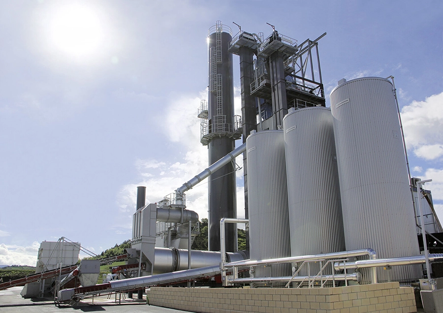
Bitumen is a viscous liquid organic binder derived from petroleum. It is extracted during the refining of crude oil. In the production of hot mix asphalt, bitumen acts as a binder, encapsulating and binding aggregate (mineral) particles and fillers, forming a homogeneous mass.
Bitumen is usually transported and stored at a temperature of about 160°C in specialized tanks with heating and heat retention systems. Maintaining this temperature ensures that the asphalt is always in a liquid state, easy to pump and measure for the mixing process.
Depending on the technical requirements of each type of asphalt concrete, asphalt types with different technical properties will be used. Therefore, modern asphalt mixing plants are often equipped with many asphalt tanks to meet the diverse needs of asphalt types and volumes.
Bitumen system
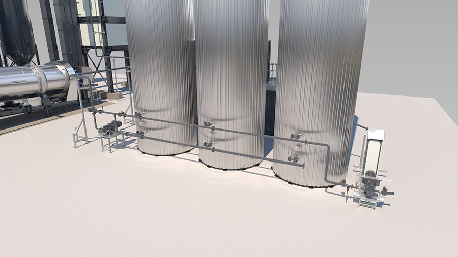
Current completed bitumen processing line
Bitumen tanks are equipped with the necessary connections for dosing and filling pipes, as well as gas transfer pipes. In the tank roof area, the inside of the tank is coated with bitumen paint. A hydrostatic level probe with minimum and maximum limiters is installed to measure the filling level. The minimum limiter switches off the tank heating when the minimum filling level is reached. The maximum limiter switches off the tank filling process when the maximum filling level is reached. In addition, an optical warning light and an audible warning signal are activated.
Two large lifting eyes in a sturdy steel structure allow easy installation. The tank is protected from heat radiation by highly efficient insulation made of mineral wool. The standard is 200 mm thick insulation, 300 mm insulation is also available. The cladding is made of profiled sheet metal.
ASPHALT PRODUCTION LINE
Weighing and mixing stage
The weighing and mixing stage is the heart of every asphalt mixing plant. All three main components are present here and are weighed and measured according to the formula. According to the mixing formula, aggregates are metered from the hot hopper stage into the mineral scale, fillers are metered from the soil silo into the filler scale and bitumen is metered from the tank into the bitumen scale. These processes run in parallel.
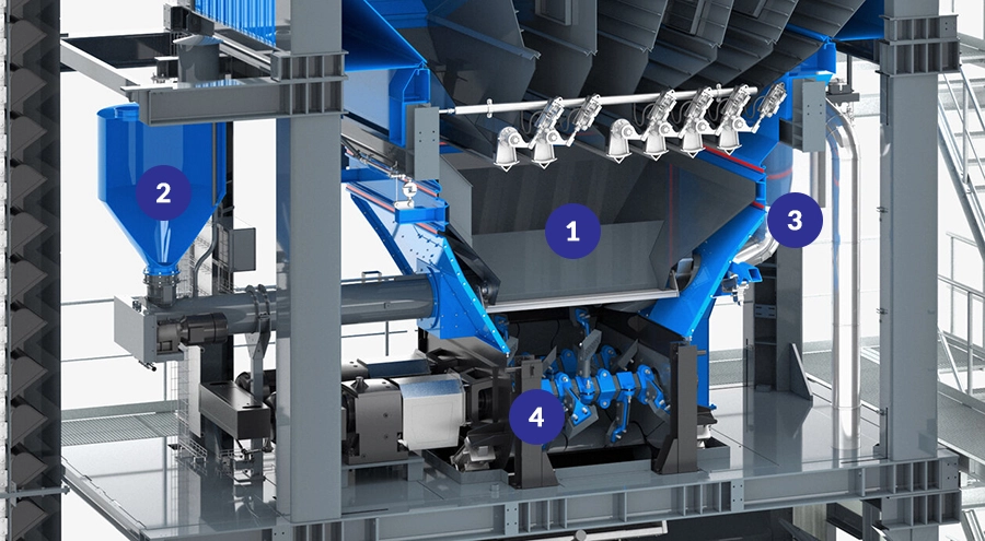
1. Mineral scale
2. Filler scale
3. Bitumen scale
4. Mixer
Due to the spacious mixer geometry, the optimum filling level for the mixer does not exceed 60%, even when the batch size is full. This contributes to a homogeneous mixing of the 3 main components and reduces wear.
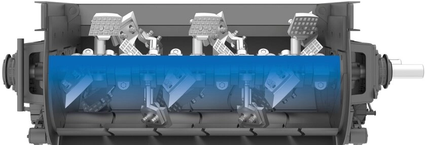
Mixer
After weighing, all materials are fed into the mixer and mixed into a homogeneous mass. The corresponding cycle is usually 45 seconds and is called a batch. The mixing capacity of the asphalt mixing plant is calculated from this cycle time, taking into account the mixer capacity, for example: With a 2 ton mixer and a cycle time of 45 seconds, this results in a mixing capacity of 160 t/h.
- Mixing capacity = mixing capacity * batch/h
- Mixing capacity = 2 tons * (3600 (seconds/h) / 45 seconds)
- Mixing capacity = 2 tons * 80 batches/h
- Mixing capacity = 160 t/h
Mixing cycle / batch
Silo containing mixed materials
Finished asphalt can be loaded onto trucks in a variety of ways.
Silo structure design below
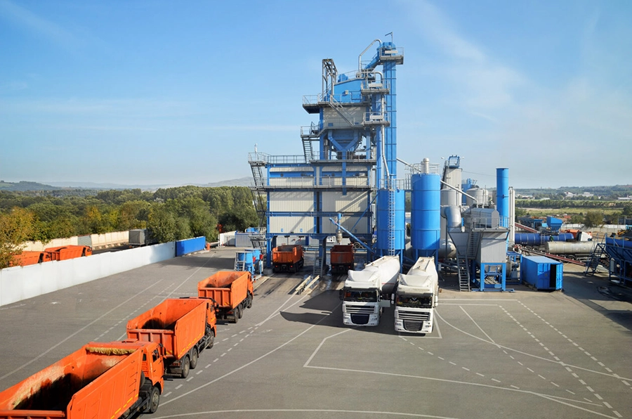
In the picture you can see the silo structure designed on the pineapple side. The silo chambers are fed individually by crawler feeders (horizontal crawlers) or through our innovation, the material mix diverter (ECO type only). Each silo chamber is equipped with a max detector (these devices prevent the silo chamber from being filled) and electrically heated discharge flaps. The silo body is insulated against heat radiation and covered with profiled sheet metal.
Material box
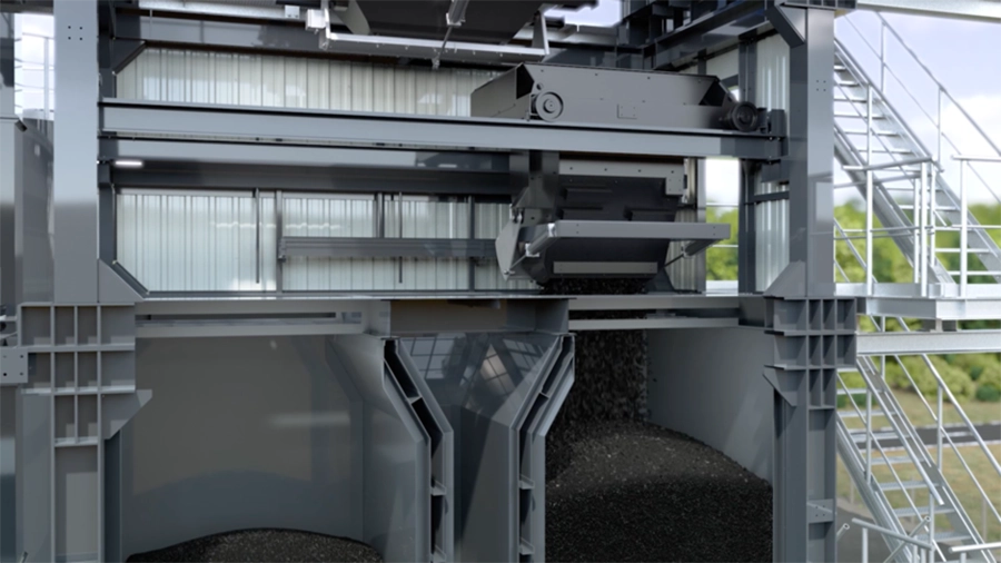
When the mixing process is complete, the mixer will pour the finished bitumen into the tank located below the mixer. The electrically controlled material tank automatically transports the mixture into the pre-selected mixed material silo. The material tank discharge cover is electrically heated and the material tank is equipped with an anti-abrasion lining.
Mixed material diverter
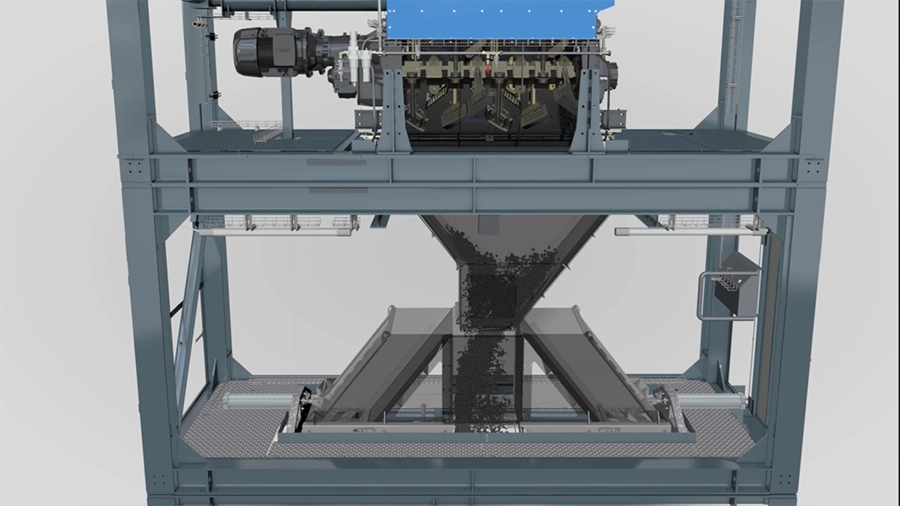
The new, patent pending mixed material diverter is a cost-effective alternative to the main tower feed bin. The system is distinguished by its simplicity, allowing quick positioning and no-load for silo selection. The output switching from the mixer is simply changed by the cylinder stroke.
Note: For ECO type batching plants only!
| Direct Loading | Single chamber silo structure located below |
| For asphalt mixing plants without loading silos, asphalt from the mixer is loaded directly into trucks. |
For asphalt mixing plants with sub-structure loading silos, the asphalt falls from the mixer directly into the silo chamber.
|
| Multi-chamber silo structure located below | Horizontal Silo |
| For asphalt concrete mixing plants with substructure loading silos, the asphalt is transported to the respective silo chamber by material bins or mixed material diverter chutes. |
For asphalt mixing plant with horizontal loading silo, asphalt is transported to the corresponding silo by inclined material bin.
|
MIXING STATION CONTROL SYSTEM
Current BENNINGHOVEN Leitsystem BLS3000 control system
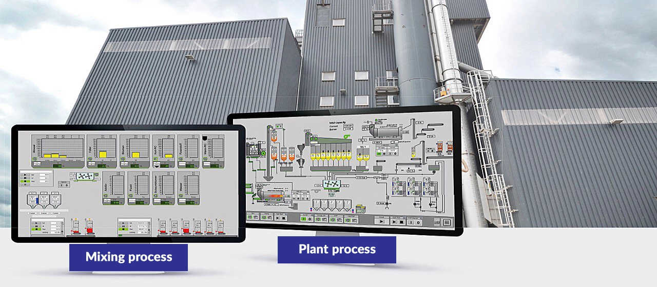
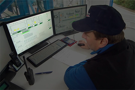
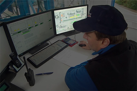
This system has been specially developed by BENNINGHOVEN to control batch-operated asphalt mixing plants. The operator controls the plant from the control cabin. The entire mixing process and the plant can be controlled and monitored on two screens.
|
Left screen: controls the mixing process
|
|
|
- Monitoring and control of the entire mixing process including pre-dosing of white mineral and recycled materials. - Post based database system for formulation, order management and reporting. - WEB reports can be queried from an external computer. - Change of recycling ratio by means of slide control during running production for both cold and hot recycling systems. |
 |
|
Right screen: station process control
|
|
 |
- Monitoring and control of the entire drying and storage process. - Simple operation via the "Auto Start" and "Auto Stop" functions. Possibility of manual control of individual components and drives. - All important set and actual values of the drying and storage process are displayed visually. - Possibility of simple error assessment. Error analysis and optimization of the batching plant based on stored values using the Trend Viewer. - All necessary station and drive parameters can be set from the control station. Due to the clear and well-structured display, as well as the simple operation, you can learn to control the system in a very short time. Malfunctions and abnormalities are displayed in clear text and can therefore be eliminated as quickly as possible. |
|
TECHNICAL SPECIFICATIONS OF STATION CONTROL SYSTEM
|
|
| STANDARD | OPTION |
| BENNINGHOVEN BLS3000 control system, switching and power supply section, air conditioning unit and low voltage main distribution | Recipe Generator for Recycling |
| 2 monitor screens | 3rd monitor screen |
| Remote maintenance system via DSL/3G | Remote maintenance system via GSM |
| High quality industrial accessories | NAS backup system |
| UPS | Connect to truck scale |
| Controller support control system | Energy monitoring |
| A4 b/w printer, A4 color printer | |
| 2nd Work Station | |
| Data Interface "RESTful Interface" | |
| Report | |
| Bitumen tank loading release | |
| Burner limited to 19.8 MW thermal power | |


